
Water Cooling Plate FSW: Leak-Free Welding for EV Power Electronics
Table of Contents
- Sealing Integrity: The Real Acceptance Criterion
- Channel and Joint Design for Leak-Free FSW Cooling Plates
- Why 6xxx Aluminum Is the Common Choice
- Joint Configurations
- Tooling and Machine Selection for Water Cooling Plate FSW
- Stationary Shoulder Tooling for Flat, Flash-Free Seams
- Retractable Pin Tools for Closed Seams
- Machine Rigidity and Force Control
- Process Parameters and Sealing Defects to Control
- Parameters That Directly Affect Seal Quality
- Defects That Matter for Sealing
- Leak Testing, Inspection, and Production Qualification
- Leak Testing
- Volumetric Inspection for Weld Soundness
- Production Qualification
- From Prototype to Production
- Plan Your Water Cooling Plate FSW Process with AEE
- Water Cooling Plate FSW: Frequently Asked Questions
- What is the best aluminum alloy for FSW water cooling plates?
- Can FSW weld thin water cooling plate lids without burn-through?
- Does FSW leave an exit hole in a sealed cooling channel?
- What leak rate can FSW water cooling plates meet?
- How do you inspect FSW water cooling plates for internal channel leaks?
- References
Water cooling plates in power electronics perform two jobs at once: they remove heat from IGBT modules, MOSFET arrays, inverters, converters, and fast chargers, and they form a sealed fluid boundary that must survive thermal cycling, pressure pulses, vibration, and years of service without a single leak. Friction stir welding (FSW) is increasingly specified for these aluminum plates because it creates solid-state welds with minimal porosity, no hot cracking, and far less distortion than fusion welding or brazing [1]. This article explains how to design, weld, inspect, and scale FSW water cooling plates for leak-free power electronics production.
Sealing Integrity: The Real Acceptance Criterion
For a power electronics cooling plate, the weld is not simply a mechanical joint. It is a pressure boundary. A visually acceptable weld can still fail if internal void channels connect the coolant path to the outside surface or if micro-porosity opens under repeated thermal load.
Friction stir welding is especially suited to this requirement because the material never melts. The tool plasticizes the metal and forges it into a continuous, fine-grained joint [1]. This mechanism avoids solidification porosity, hot cracking, and gas entrapment that can create leak paths in fusion-welded aluminum. High-quality aluminum FSW is covered by ISO 25239-5, which defines inspection levels and acceptance requirements for production welds [2]. For aerospace-derived power electronics assemblies, AWS D17.3 adds a recognized framework for process qualification and workmanship [3].
The key performance issue is not strength alone. It is tightness. Sealed cooling plates must be tested with methods that can detect extremely small leakage paths, not just obvious defects. The correct leak-test method should match the specified acceptance level; tracer-gas and pressure-decay methods are standard when the plate must provide long-term fluid containment [4].
Channel and Joint Design for Leak-Free FSW Cooling Plates
Most water cooling plates start as two machined aluminum components: a channel plate and a lid. The channel plate has a serpentine or parallel flow path machined into one face, and the lid covers that open channel. The weld must run close to the channel edges without breaking into the channel and must remain continuous across the entire sealing path.
Why 6xxx Aluminum Is the Common Choice
6061 and 6063 are widely used for liquid cooling plates because they offer a practical balance of thermal conductivity, machinability, availability, and corrosion resistance. FSW welds 6xxx-series material well, producing joints that maintain most of the parent material strength with predictable heat input [1][2]. Other alloys may be used when the cooling plate is part of a larger structural housing, but the lid-to-channel joint is usually designed around a 6xxx base material.
Joint Configurations
Three joint arrangements are common:
- Lap joint over the channel: The lid overlaps the channel wall by 6–15 mm, depending on channel width and clamping. This is the most common configuration for flat cooling plates.
- Butt joint with a raised channel wall: A machined wall is welded to the lid along the top edge. This reduces the sealed footprint but demands tighter fit-up and tool-position control.
- Integral lid design: A thicker plate is joined to the channel plate with a single continuous seam; this is preferred when the weld must be machined flat after welding.
For all configurations, the weld centerline must be controlled relative to the channel edge. Too close to the channel risks tool breakthrough. Too far away wastes material and creates a thicker unsealed land that may distort. The engineering goal is to keep the weld root outside the fluid path while providing full penetration into the lid material.
Tooling and Machine Selection for Water Cooling Plate FSW
Water cooling plates are thin in cross-section, often 3–12 mm total, and they contain internal channels. This makes them sensitive to tooling choices that would be less critical in a thick structural weld.
Stationary Shoulder Tooling for Flat, Flash-Free Seams
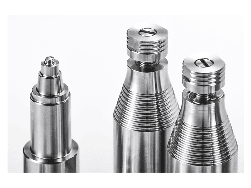
Stationary shoulder FSW tools keep the outer shoulder from rotating while the pin rotates. This reduces heat input, produces a smooth crown, and prevents aggressive thinning of the lid. For thin-wall cooling plates, this can mean less flash, tighter thickness control, and less post-weld machining on the sealing surface.
AEE offers stationary shoulder tooling for aluminum from 1.0 mm upward, which is directly relevant to thin-lid cooling plates and power electronics housings.
Retractable Pin Tools for Closed Seams
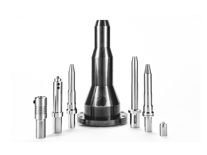
A standard FSW tool leaves an exit hole when the tool is withdrawn. In a water cooling plate, an exit hole in the sealing path is unacceptable. A retractable pin tool gradually withdraws the pin into the shoulder at the end of the weld, allowing the plasticized material to fill the exit location before the shoulder disengages. This produces a sealed weld end without a keyhole and is especially useful for closed-loop or circular channel welds.
Machine Rigidity and Force Control
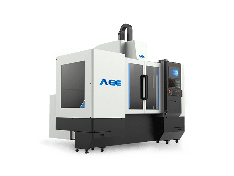
Sealing quality depends on consistent plunge depth, welding force, and travel speed. A machine with good structural rigidity and closed-loop force control is preferable because it holds the tool at a stable position even as the plate heats and distorts locally.
For water cooling plate development and small-to-medium production, AEE’s C-type FSW Machine provides a compact work envelope, 30 kN Z-axis force, 4,000 rpm spindle speed, and process monitoring for force, position, torque, and temperature. Its working thickness covers the typical water cooling plate range, and its stated capacity supports welding depths up to 8 mm with speeds up to 3,500 mm/min depending on the joint and alloy.
For sealed power electronics enclosures where linear seams may be combined with spot sealing operations, exit-hole management is critical. <Refill Friction Stir Spot Welding (RFSSW)> covers exit-hole-free spot welding for thin aluminum enclosures and closures.
Process Parameters and Sealing Defects to Control
A leak-free FSW cooling plate is the result of a qualified parameter window, not a single fixed recipe. The correct settings depend on alloy, thickness, tool design, channel location, and fixture behavior.
Parameters That Directly Affect Seal Quality
- Rotation speed controls heat generation and material flow. Excessive rotation can create flash and over-soften the material; insufficient rotation can produce lack of fill.
- Travel speed controls heat per unit length. Too high may leave a rough root or tunnel defect; too low can create excessive flash and reduce production efficiency.
- Axial force or plunge depth keeps the shoulder in contact with the plate surface. In lap welds over channels, inconsistent force can create root flaws or incomplete sealing.
- Tool tilt influences material consolidation and root closure. For water cooling plates, the goal is to produce a fully consolidated root without penetrating the coolant channel.
- Clamping and backing must keep the lid and channel plate in close contact. A small gap can create a root defect that is extremely difficult to detect after weld dressing.
Defects That Matter for Sealing
The most serious FSW defects for cooling plates are internal channels that can form a leak path:
- Tunnel defects are continuous or intermittent voids along the weld. If a tunnel intersects the cooling channel or the outside surface, the weld will leak.
- Root lack of fill occurs when the pin does not fully consolidate material at the bottom of the joint. In a lap joint over a channel, this can leave an unbonded edge precisely where the fluid boundary must be sealed.
- Hooking and cold lap in lap joints can create a sharp interface that opens under thermal cycling, even if the weld looks acceptable on the surface.
- Exit-hole defects from conventional tools become leak points unless the weld is terminated outside the fluid boundary or a retractable pin tool is used.
A qualified welding procedure should address these defects before production. ISO 25239-5 provides quality levels and inspection requirements for aluminum FSW; the selected acceptance level should be based on the consequence of a leak in service [2]. If the part also has aerospace application requirements, AWS D17.3 can be used as a qualification reference [3].
Need a parameter window for your specific plate design? Contact the AEE process team at [email protected] with your alloy, channel depth, lid thickness, and leak-rate target. The team can recommend a test matrix and, if suitable, weld first-article samples on an AEE C-type or gantry machine.

Leak Testing, Inspection, and Production Qualification
No production welding process for sealed cooling plates is complete without a leak-test method that can detect the smallest unacceptable leak path.
Leak Testing
Tracer-gas testing using helium or forming gas is common for power electronics cooling plates because it is sensitive and can be localized to specific weld sections. ISO 20485 describes tracer-gas leak-test methods [4]. Pressure-decay testing is also widely used on production lines; the plate is pressurized, isolated, and monitored for pressure drop. Water-submersion testing can find larger leaks but may miss the fine leakage rates relevant to long-term electronics service.
The test should be performed after machining or weld dressing because post-weld processes can remove near-surface material and expose a shallow defect that was not detected before machining.
Volumetric Inspection for Weld Soundness
Visual inspection is useful but not sufficient. X-ray or computed tomography can reveal internal voids, tunnels, and root flaws [3]. Ultrasonic testing can also be applied to FSW aluminum welds; inspection should follow the requirements and assessment levels appropriate to the weld class [5]. For cooling plates, the priority is to match the inspection method to the defect orientation. A planar root flaw may need a different probe angle than a round tunnel defect.
Production Qualification
For serial production, the FSW process should be qualified with tests that reproduce the actual production condition: same alloy, same joint configuration, same tool life stage, same clamping, and the same machine. The qualification should include leak testing, metallographic sections, and tensile or peel tests as appropriate for the joint type. ISO 25239-5 provides a structured path for welder and procedure qualification [2], and AWS D17.3 offers an aerospace-oriented framework when the power electronics application demands it [3].
For power electronics assemblies that join aluminum cooling plates to copper busbars or conductor interfaces, process control and intermetallic formation become more demanding. <Customized Dissimilar Material Welding Manufacturers in China> covers custom dissimilar-material FSW solutions for aluminum-copper joints.
From Prototype to Production
The transition from prototype to production should not change the fundamental process. AEE’s philosophy is to keep process development and production on the same machine family and the same tooling concept. This avoids the common problem of qualifying a weld on a laboratory machine and then finding that the production machine cannot reproduce the force, travel, or thermal conditions.
For water cooling plates, this usually means starting on a rigid C-type machine for process development, then moving to a gantry machine or an automated line when output volume increases. The key is to retain force control, positional accuracy, and data logging across the whole chain.
Plan Your Water Cooling Plate FSW Process with AEE
AEE is a high-tech FSW enterprise headquartered in Suzhou with mass production in Liyang, covering 55,000 square meters. The company supplies standard and customized FSW machines, pin tools, production lines, and process services for sealed aluminum components including water cooling plates, radiators, motor shells, and battery trays.
Send your cooling plate drawing, material grade, channel cross-section, and leak-rate target to [email protected] or call +86 18325808715. AEE can evaluate the joint design, recommend the tool and machine, and weld first-article samples before you commit to equipment.
Water Cooling Plate FSW: Frequently Asked Questions
What is the best aluminum alloy for FSW water cooling plates?
6061 and 6063 are common choices because they weld well with FSW, machine cleanly, and offer a practical balance of thermal conductivity, cost, and corrosion resistance. The final selection should consider the coolant chemistry, operating temperature range, and whether the plate is structural.
Can FSW weld thin water cooling plate lids without burn-through?
Yes. Because FSW operates below the melting point, it avoids the burn-through risk associated with fusion welding. Stationary shoulder tooling further reduces heat input and helps maintain lid thickness for thin cover plates.
Does FSW leave an exit hole in a sealed cooling channel?
A conventional FSW tool leaves an exit hole when withdrawn. For sealed plates, the weld should be terminated outside the fluid boundary or a retractable pin tool should be used so the pin withdraws while the material fills the exit location.
What leak rate can FSW water cooling plates meet?
The achievable leak rate depends on the joint design, alloy, tooling, parameter window, and inspection method. Properly qualified FSW plates are regularly tested by pressure decay or tracer-gas methods; the acceptance level should be defined for the specific application and verified with the production process.
How do you inspect FSW water cooling plates for internal channel leaks?
Production inspection usually combines leak testing with volumetric weld inspection. Tracer-gas or pressure-decay testing evaluates tightness, while X-ray, CT, or ultrasonic testing detects internal weld defects such as tunnels or root lack of fill. Visual inspection alone is not sufficient for sealing surfaces.
References
[1] TWI Ltd. Friction Stir Welding. https://www.twi-global.com/technical-knowledge/job-knowledge/friction-stir-welding-147/
[2] ISO 25239-5:2020. Friction stir welding — Aluminium — Part 5: Quality and inspection requirements.
[3] AWS D17.3/D17.3M:2020. Specification for Friction Stir Welding of Aluminum Alloys for Aerospace Applications.
[4] ISO 20485:2017. Non-destructive testing — Leak testing — Tracer gas method.
[5] ISO 17640:2018. Non-destructive testing of welds — Ultrasonic testing — Techniques, testing levels, and assessment.
If you’re interested, check out these related articles:
Customized Dissimilar Material Welding Manufacturers in China
Refill Friction Stir Spot Welding (RFSSW)