
FSW in Automotive: 8 Aluminum Parts Worth Welding Today
Table of Contents
- Why FSW Is Gaining Ground in Automotive Aluminum Joining
- Eight Aluminum Components You Can Weld with FSW Today
- 1. Battery Trays and Enclosure Frames
- 2. Liquid Cooling Plates
- 3. E-Motor, Inverter, and Converter Housings
- 4. Aluminum Wheel Hubs and Rims
- 5. Subframes and Chassis Nodes
- 6. Power Busbars and Conductors
- 7. Crash-Management Beams
- 8. Seat Frames and Lightweight Brackets
- Process Requirements That Decide Feasibility
- Tooling, Machines, and Automation Considerations
- Application-Specific FSW Assessment
- FAQ
- Which aluminum alloys are most suitable for automotive FSW?
- What thickness range is practical for FSW automotive components?
- How does FSW compare with laser welding for battery trays?
- Does FSW require a specialized machine for each of the eight components?
- References
Aluminum-intensive vehicle programs no longer ask whether friction stir welding can join automotive structures. The practical question is where to apply it first. Battery trays, cooling plates, motor housings, wheels, and structural extrusions all carry aluminum joints that fusion welding often compromises with porosity, hot cracking, or distortion. Friction stir welding joins aluminum below the melting point, producing a forged, solid-state joint with less distortion and stronger process control in production [1][2].
Why FSW Is Gaining Ground in Automotive Aluminum Joining
Fusion welding of 5xxx and 6xxx automotive alloys requires careful filler selection, gas shielding, and heat management. FSW replaces the liquid-to-solid transformation with a rotating non-consumable tool that plasticizes, stirs, and forges material along the joint line [2]. The weld forms without melting, so many porosity and hot-cracking mechanisms disappear before inspection even begins [1]. For automotive manufacturing, this means no filler wire, no shielding gas, lower distortion, and a process that responds well to force-controlled automation.
The economic case is strongest on high-value aluminum assemblies: sealed enclosures, safety-critical extrusions, and parts where post-weld straightening or leak repair erodes margin. When the same FSW cell can process a family of components by changing fixture, tool, and weld path, machine utilization improves compared with part-dedicated fusion cells.
Eight Aluminum Components You Can Weld with FSW Today
The following eight component families are the most repeatable automotive FSW targets. They share flat or gently curved joint paths, enclosed or sealed requirements, or production volumes where consistent joint quality justifies the fixture and tooling investment.
| No. | Component family | Typical FSW joint | Main production benefit |
|---|---|---|---|
| 1 | Battery tray and enclosure frame | Long butt or lap seams in extrusions | Leak-tight, low-distortion structure |
| 2 | Liquid cooling plate | Lap and channel-cover joints | Porosity-free watertight channels and flat cover surfaces |
| 3 | E-motor, inverter, and converter housing | Circular and linear closure welds | Sealed enclosures with low distortion |
| 4 | Aluminum wheel hub and rim | Circumferential joint | Keyhole-free circular welds with retractable tools |
| 5 | Subframe and chassis node | Butt joints in extruded or cast sections | Higher joint consistency and reduced rework |
| 6 | Power busbar and conductor | Lap joints in aluminum/copper stacks | Low-resistance solid-state interface |
| 7 | Crash-management beam | Butt or lap seams in profiles | Repeatable energy-absorption structure |
| 8 | Seat frame and lightweight bracket | Lap and spot welds | Rivet-free spot joining with flat surfaces |

1. Battery Trays and Enclosure Frames
Battery enclosures combine long extruded side rails, cross members, base plates, and mounting flanges. FSW is well suited to these long straight seams because it produces low-distortion joints at production speeds without filler wire. A gantry or long-bed FSW machine can weld full-length tray profiles, and the solid-state joint helps maintain leak-tightness for sealed enclosure sections. The design can also use gantry FSW machine platforms for 2D seam paths and larger tray layouts.
2. Liquid Cooling Plates
Cold plates may use thin 3xxx, 5xxx, or 6xxx covers joined to channeled base plates. Fusion processes can introduce porosity that creates leak paths. FSW produces a continuous forged seal with a flat cover surface, which becomes important when power electronics require direct thermal interface contact. For prototype and medium-volume cold plate work, C-type FSW Machine platforms provide the needed rigidity and small footprint.
3. E-Motor, Inverter, and Converter Housings
Housing welds often require a sealed linear or circumferential seam after internal components are placed. FSW reduces thermal distortion around machined bores and bearing seats compared with fusion welding. Retractable pin tools are useful here because they remove the exit keyhole on closed-contour welds, leaving a fully sealed, machinable surface.
4. Aluminum Wheel Hubs and Rims
Automotive wheel manufacturing has been one of the clearest FSW automation cases. A rotary FSW station can join forged or flow-formed rim sections to hub components with consistent circumferential welds. Retractable tools eliminate keyhole defects, while automated loading, unloading, and weld tracking keep cycle times stable. AEE’s Automatic FSW Production Line for Aluminum Alloy Wheel demonstrates the process: the line handles wheel diameters from 17 to 22 inches and weld thickness from 1.2 to 10 mm, with laser tracking, QR code traceability, and quality judgment built into the cell.
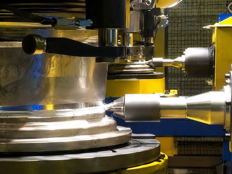
In production, circular joints and closed-contour welds often need exit-hole-free results. <AEE provides customer with optional features FSW tool> covers how retractable and optional tool features remove exit holes in automated FSW cells.
5. Subframes and Chassis Nodes
For cast or extruded subframe nodes, FSW can join thick sections without the same heat-affected-zone softening associated with fusion repair. The process is most valuable where engineers want a repeatable butt joint with minimal post-weld straightening. It also supports dissimilar aluminum grades, allowing a high-strength node to be joined to a formable energy-absorption rail.
6. Power Busbars and Conductors
Copper-to-aluminum busbar joints are increasingly common in EV power distribution. FSW can create a thin, continuous intermetallic layer and a strong solid-state contact without melting either base metal. The result is better electrical and mechanical consistency than many bolted or fusion welded alternatives. Because copper requires higher forge force and torque, machine stiffness and spindle torque selection become critical.
Aluminum-to-copper busbar transitions and dissimilar automotive joints remain challenging for fusion processes. <Customized Dissimilar Material Welding Manufacturers in China> covers how tailored FSW processes address aluminum-to-copper and dissimilar joints in production.
7. Crash-Management Beams
Bumper beams and crash rails often use aluminum extrusions. FSW delivers predictable longitudinal seams with fewer porosity-related weak points. This helps maintain the energy-absorption path in a collision while reducing the need for fusion-specific filler or shielding gas.
8. Seat Frames and Lightweight Brackets
For thin-gauge aluminum seat frames and brackets, friction stir spot welding or refill friction stir spot welding can replace rivets and resistance spot welds. The spot joint is flat, strong, and does not add fastener weight. This is especially useful for mixed-material seat structures and battery-pack internal brackets.
For spot-joined aluminum body panels or seat structures, a completely filled surface is critical. <Refill Friction Stir Spot Welding (RFSSW)> covers how exit-hole-free spot joints improve surface quality and static strength.
If your team is evaluating one of these eight part families, send the joint geometry and target volume to [email protected] or call +86 18325808715. A confidential feasibility review can be completed before any machine decision.
Process Requirements That Decide Feasibility
Not every aluminum part is an automatic FSW fit. The process demands rigid fixturing, a stiff machine structure, and enough forge force to keep the tool shoulder in contact with the workpiece. Part geometry must give the tool access to the joint line; deep interior corners and very short seams can make tooling awkward. Automotive teams usually evaluate five items:
- Alloy family and temper. Heat-treatable 6xxx and 7xxx alloys can be welded, but process windows differ [1].
- Thickness and joint type. Thin sheets may need precise flatness control; thick sections require higher spindle torque and forge force.
- Seam path. Linear and large-radius seams are easiest; small-radius corners may require specialized 2D or 3D machine configurations.
- Sealing requirements. Retractable tools or bobbin tools help eliminate exit holes on closed contours.
- Cycle time and automation. Pin tool life, tool change management, and weld tracking systems become critical at production volumes.
For validation, process qualification can follow ISO 25239 for aluminum friction stir welds [1]. Aerospace-derived automotive programs may also reference AWS D17.3 for weld class and inspection guidance [3]. If the intended application is safety-critical, the team should align internal weld class requirements with the appropriate customer standard before starting sample welding.
Tooling, Machines, and Automation Considerations
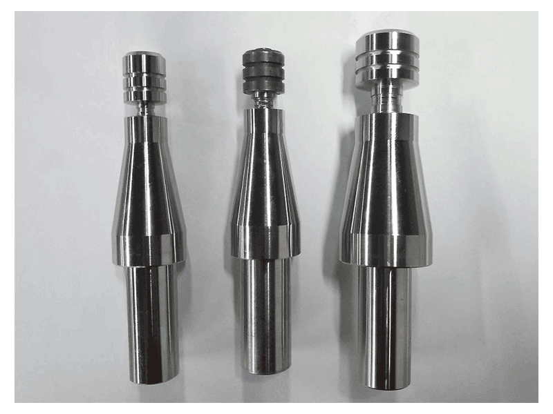
Tool selection is as important as machine selection. A conventional threaded pin tool covers many open-seam applications in 5xxx and 6xxx alloys. Bobbin tools weld hollow profiles and remove the need for rigid backing support, which matters for battery tray sections and closed extrusions. Stationary shoulder tools reduce heat input and give a smoother surface on thin-wall covers. Retractable tools eliminate exit keyholes on circular or closed-contour joints. AEE’s FSW pin tool portfolio spans conventional, retractable, bobbin, stationary shoulder, and FSSW versions for aluminum thickness ranges from 1.0 mm upward.
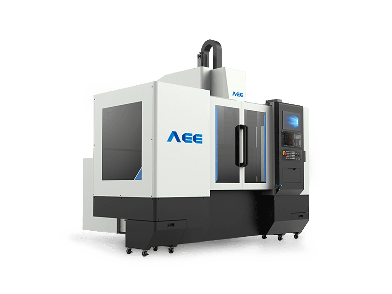
Machine selection follows weld length, part size, and production rate. C-type machines fit smaller plates, housings, and cold plates. Gantry machines cover large trays and structural profiles. Long-bed machines serve rail-style extrusions, and 3D machines address curved automotive closure surfaces. Production lines for wheels add rotary axis control, automated loading, laser tracking, and retractable tool control. For battery tray production, a double-head FSW machine can weld both sides of a joint in one setup, reducing distortion and increasing throughput.
If you are benchmarking tool or machine options for one of these eight parts, send a part drawing, material specification, and target cycle time to [email protected] or call +86 18325808715. AEE can map the component to a specific C-type, gantry, or automated cell and arrange sample welding before capital approval.
Application-Specific FSW Assessment
If you are deciding between FSW, laser welding, or MIG for an automotive aluminum component, start with a weldability study, not a machine quote. Send a 2D step or drawing, alloy grade, temper, joint thickness, required leak rate or structural requirement, and target annual volume to [email protected] or +86 18325808715. AEE engineers can recommend a tool type, machine platform, fixture strategy, and sample-welding plan, then support process qualification through production launch.
FAQ
Which aluminum alloys are most suitable for automotive FSW?
In automotive work, the most common groups are non-heat-treatable 5xxx and heat-treatable 6xxx alloys. 2xxx and 7xxx alloys can be friction stir welded, but they are more common in aerospace and high-performance applications where process windows and tool wear are managed more tightly [1]. Each alloy family should be evaluated with sample welds because temper, thickness, and joint configuration shift the usable parameter range.
What thickness range is practical for FSW automotive components?
FSW spans thin sheet, plate, and hollow profiles. The practical thickness range depends more on machine force, spindle torque, and backing than on the process itself. In the eight examples above, standard C-type and gantry machines cover most automotive thicknesses, while heavy-load platforms extend capability to much thicker sections.
How does FSW compare with laser welding for battery trays?
Laser welding is fast and can produce narrow seams, but it requires precise edge preparation, air gap control, and careful management of porosity. FSW is more tolerant of aluminum oxide, produces a forged joint without filler wire, and typically shows lower distortion across long seams [1][2]. The trade-off is that FSW requires strong fixturing and applies higher forces to the part. For long, leak-tight battery tray seams, FSW is often preferred when distortion and leak reliability dominate the decision.
Does FSW require a specialized machine for each of the eight components?
No. A C-type or gantry FSW machine can handle multiple part families with different fixtures and tools. A dedicated automated line is justified only when annual volume, cycle time, and part geometry are stable. Many teams start with a sample-welding study on an application-specific fixture before committing to a full system.
References
[1] ISO 25239:2023, Friction stir welding — Aluminium, International Organization for Standardization.
[2] TWI Ltd., Friction Stir Welding: Process and Applications, https://www.twi-global.com/technical-knowledge/job-knowledge/friction-stir-welding-147/
[3] AWS D17.3/D17.3M, Specification for Friction Stir Welding of Aluminum Alloys for Aerospace Applications, American Welding Society.
If you’re interested, check out these related articles:
AEE attend 13th International Symposium on FSW in Kyoto, Japan on 21 – 23 May 2024
AEE provides customer with optional features FSW tool
Refill Friction Stir Spot Welding (RFSSW)