
FSW for EV Inverter & Converter Housings: Leak-Free Sealing
Table of Contents
- The Sealing Challenge in EV Power Electronics Housings
- Why FSW Fits Sealed Aluminum Enclosures
- Material Selection and Joint Design
- Process Parameters and Quality Control for Leak-Proof Welds
- Tooling and Equipment for High-Integrity Housing Welds
- From Feasibility to Production Qualification
- End CTA
- FAQ
- Why is FSW preferred over fusion welding for sealed aluminum housings?
- Can FSW produce a completely keyhole-free weld on a closed housing contour?
- What leak rate can a properly qualified FSW housing weld achieve?
- Is FSW suitable for cast aluminum inverter and converter housings?
- References
Friction stir welding (FSW) is a solid-state joining process that uses a rotating, non-consumable tool to plasticize and forge aluminum without reaching the material’s melting point. For EV inverter and converter housings, that single distinction drives most of the process decisions. A sealed aluminum enclosure must protect power electronics from coolant, moisture, and road contaminants for the full service life of the vehicle, and it must do so without porosity, cracking, or distortion that would create leak paths after assembly.
The Sealing Challenge in EV Power Electronics Housings
Inverter and converter housings differ from structural automotive parts in one critical way: the weld is not simply a load-bearing connection. It is also the primary environmental barrier for high-voltage power electronics. A housing that passes mechanical testing but fails leak testing is unusable.
FSW addresses this challenge through the physics of the process itself. Because the aluminum remains below its solidus temperature, the weld zone does not solidify from a liquid pool. This eliminates gas porosity, solidification cracking, and hot tearing—defect classes that fusion welding must control through filler material selection, shielding gas, and rework. In FSW, the joint is forged from plasticized material, producing a continuous, fully dense nugget when the process window is correctly established [1].
The second sealing risk is distortion. Fusion welding introduces high, localized heat input that can pull machined sealing faces out of tolerance. FSW uses lower heat input and distributes it across the shoulder contact area, which reduces distortion and preserves flatness on O-ring grooves, lid seats, and connector faces. This is especially important for enclosures that must meet IP67-level protection against temporary immersion [3].
Common sealing verification methods for inverter and converter housings include:
| Test method | What it detects | Typical production use |
|---|---|---|
| Pressure decay | Gross-to-fine leak paths in pre-assembled housings | 100% inline screening |
| Helium leak detection | Micro-leaks in sealed weld seams and joints | Process qualification and sampling |
| IP67 immersion | Liquid ingress under defined pressure and time | Validation and design release |
| Dye penetrant | Surface-breaking weld defects | Weld inspection after machining |
Why FSW Fits Sealed Aluminum Enclosures
A leakage-proof housing weld must meet several requirements at once. FSW handles them through inherent process characteristics and machine-controlled repeatability.
| Housing requirement | FSW response |
|---|---|
| No porosity or hot cracks | Solid-state forging avoids solidification defects [1] |
| Tight sealing surfaces | Lower distortion preserves machined geometry |
| Repeatable weld quality | Spindle speed, travel speed, and Z-axis force are servo-controlled |
| No filler or shielding gas | Reduces process variables and consumable cost |
| Traceability | Force, torque, and temperature data can be logged per weld |
Because the rotating tool continuously forges the joint under axial force, a properly qualified FSW seam carries no filler-related contamination. The seal quality depends on tool geometry, welding parameters, and fixture rigidity—all of which can be standardized and monitored. This is why FSW has become the preferred route for many closed-contour aluminum enclosures where leakage means complete functional failure.
Material Selection and Joint Design
EV inverter and converter housings are typically produced from 6xxx wrought alloys, cast aluminum, or a combination of both. Each material group needs a slightly different FSW strategy.
| Alloy and form | Typical role | FSW consideration |
|---|---|---|
| 6061-T6 machined frame | Housing body or lid seat | Good weldability; control heat input to limit HAZ softening |
| A356/A357 cast base | Converter or inverter enclosure | Requires clean cast surfaces and validated pin profile; oxide layers must be fragmented |
| 6063/6082 extrusion | Cooling-channel walls or stiffened covers | Strong FSW response with stable material flow |
| 5xxx sheet or lid | Cover plates | Good weldability; select shoulder geometry to limit flash |
Joint design should prioritize full penetration at the root and a smooth exit strategy. Closed-contour welds—common when a lid is welded around the entire perimeter of an enclosure—demand a tool solution that can terminate the weld without leaving a keyhole. A standard fixed-pin tool withdraws and leaves an exit hole. In a sealed housing, that keyhole is a direct leak path. This makes retractable-pin FSW mandatory for closed-loop lid welds when no secondary plugging operation is permitted [1].
Process Parameters and Quality Control for Leak-Proof Welds
FSW parameter development is not a single-number exercise. The working window is defined by the interaction of rotation speed, travel speed, axial force, tool tilt, and plunge depth. For 6xxx aluminum housings, the target is a fully consolidated stir zone with a continuous surface and no root defects.
The most common FSW defects with sealing consequences are not cosmetic. A tunnel or wormhole defect forms when heat input is too low for the travel speed, leaving an internal channel that can connect the weld interior to the root or face. A kissing bond may appear consolidated on the surface but contains an oxide line with poor mechanical and sealing integrity. Root lack of penetration is the most direct sealing risk because it creates a continuous path under the weld.
| Defect type | Typical cause cluster | Prevention strategy |
|---|---|---|
| Tunnel or wormhole | Low heat input or excessive travel speed | Reduce travel speed or increase rotation/force |
| Kissing bond | Insufficient oxide fragmentation or mixing | Adjust pin profile, Z-force, and penetration depth |
| Root lack of penetration | Pin length or plunge depth inadequate for joint geometry | Validate tool geometry against actual housing thickness |
| Flash | Excess heat or shoulder contact pressure | Optimize tilt, plunge depth, and shoulder diameter |
Process qualification should follow a structured welding procedure specification approach. ISO 25239 provides the framework for FSW procedure qualification and quality levels for aluminum [1]. For higher-reliability requirements, additional validation based on aerospace-grade FSW practices can provide conservative acceptance criteria [2]. Real-time monitoring of spindle torque, Z-axis force, and tool temperature adds the process data needed to catch drift before a leak rate shifts out of tolerance.
Tooling and Equipment for High-Integrity Housing Welds
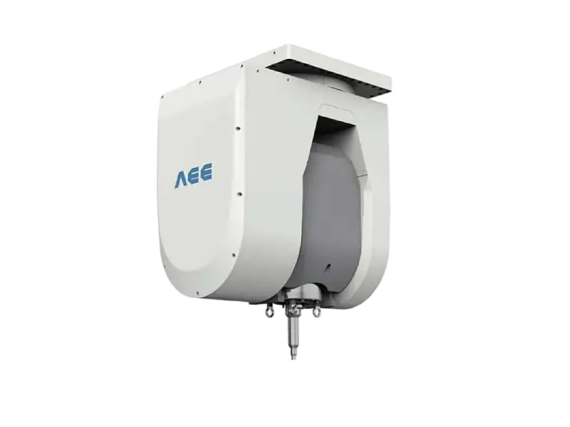
Tooling selection determines whether a sealed enclosure weld is stable in production. For closed-contour inverter and converter housings, the retractable FSW tool is the most common starting point. The shoulder and pin operate independently; near the weld end, the pin retracts under machine control and the plasticized material fills the exit hole. The result is a keyhole-free weld around the entire housing perimeter. This removes the need for plugging, friction stud repair, or secondary machining [1].
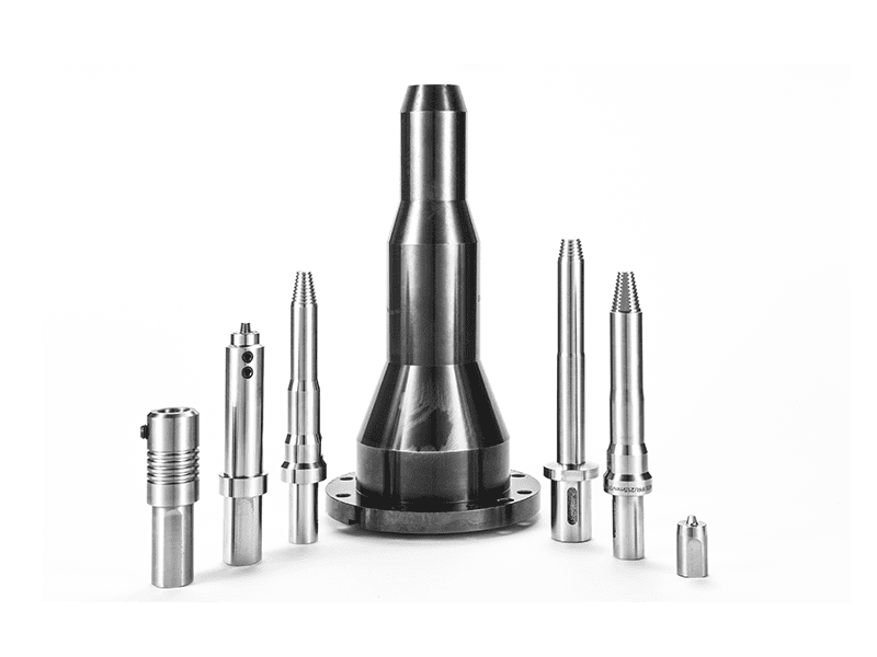
For thin-wall covers and cast surfaces where surface finish and low heat input are critical, stationary-shoulder FSW is a complementary option. The shoulder remains fixed while only the pin rotates, reducing heat input and producing a smoother crown with lower distortion. This is useful when the weld lies near a machined sealing face or when flash must be minimized before anodizing or plating.
For closed-contour housing welds, <AEE provides customer with optional features FSW tool> covers how retractable-pin and stationary-shoulder tool configurations are selected to remove exit holes and improve surface quality.
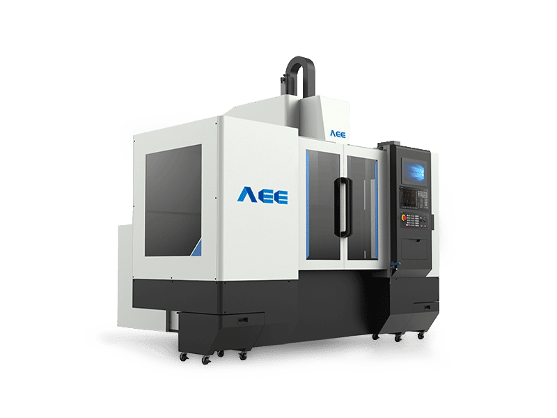
Equipment selection follows the same logic. A C-type FSW machine with force control fits smaller housings, prototype runs, and process development. Gantry-type machines handle larger inverter housings, dual-station production, and fixtures with automated loading. The key machine requirements are Z-axis force capacity, spindle torque stability, and a control architecture that can log process data for every weld.

From Feasibility to Production Qualification
A leak-free FSW process is rarely proven by welding a single part. The standard route is: sample welding on production-representative material, cross-section inspection, leak testing, parameter lock-in, then qualification. This sequence catches root-face geometry mismatches early, before hard tooling and fixtures are finalized.
The most common qualification failures come from three sources: cast material with subsurface porosity near the weld root, fixture clamping that cannot hold the joint closed under axial force, and tool pin length selected from nominal drawings instead of measured housing geometry. A supplier that can run sample welds on your actual alloy and wall thickness reduces the risk of discovering these problems after the production line is installed.
If you are qualifying an inverter or converter housing for leak-tight FSW, send your 2D or 3D housing drawings, target leak rate, and production volume to [email protected] or call +86 18325808715 for a process assessment and sample-weld plan.
End CTA
Ready to qualify a leak-proof FSW process for your EV inverter or converter housing? Contact Aerospace Engineering Equipment at [email protected] or +86 18325808715 with your part drawings, alloy, wall thickness, and target leak rate. We provide sample welding, process development, tooling, and turnkey equipment matched to your sealed-enclosure production line.
FAQ
Why is FSW preferred over fusion welding for sealed aluminum housings?
FSW joins aluminum without melting it. This eliminates gas porosity, solidification cracking, and hot tearing, which are the fusion-welding defect classes most likely to create leak paths in a sealed housing. The process also produces lower distortion, helping preserve the flatness of machined sealing surfaces and O-ring grooves.
Can FSW produce a completely keyhole-free weld on a closed housing contour?
Yes. A retractable-pin FSW tool gradually withdraws the pin into the shoulder as the weld completes, allowing plasticized material to fill the exit hole. This produces a continuous, keyhole-free weld around the entire perimeter without requiring a secondary plugging or repair operation.
What leak rate can a properly qualified FSW housing weld achieve?
The achievable leak rate depends on material quality, joint design, tooling, and process control rather than on FSW’s fundamental limits. Many sealed aluminum power electronics housings are validated by helium leak testing and IP67 immersion testing after process qualification. The key is proving the process window on production-representative material before locking tooling and fixtures.
Is FSW suitable for cast aluminum inverter and converter housings?
Yes, but cast aluminum requires careful surface preparation and a validated pin profile. Subsurface porosity near the weld root inherited from the casting process can affect sealing if the joint root is not properly placed. A sample-weld program on the actual casting geometry is the most reliable way to confirm feasibility before investment.
References
- ISO 25239:2023, Friction stir welding — Aluminium. International Organization for Standardization.
- AWS D17.3/D17.3M, Specification for Friction Stir Welding of Aluminum Alloys for Aerospace Applications. American Welding Society.
- IEC 60529, Degrees of protection provided by enclosures (IP Code). International Electrotechnical Commission.
If you’re interested, check out these related articles:
Customized Dissimilar Material Welding Manufacturers in China
Refill Friction Stir Spot Welding (RFSSW)
AEE attend 13th International Symposium on FSW in Kyoto, Japan on 21 – 23 May 2024