
FSW for E-Motor Housings & Electric Control Boxes
Table of Contents
- Why FSW Fits E-Motor Housings & Electric Control Boxes
- Joint Design & Alloy Selection for Sealed Housings
- Leak-Tight Welding: Coolant-Channel & Seal-Path Control
- Tooling Strategy for Closed-Contour & Thin-Wall Welds
- Process Parameters & Heat-Input Control
- Quality Control & Leak Verification
- Production Planning & Machine Configuration
- Next Step: Send Your E-Motor Housing Drawing for Review
- FAQ
- Is FSW suitable for thin-wall electric control box covers?
- Can FSW weld a closed circular coolant channel without leaving an exit hole?
- What aluminum alloys are used for e-motor housings and control boxes?
- How do you verify leak-tightness after FSW?
- Which FSW configuration is best for e-motor housings?
- Does FSW require a backing plate for every housing weld?
- References
Electric drive housings sit at the intersection of two difficult requirements: they must remain light and stiff, and they must stay sealed for the full service life of the vehicle. Friction stir welding (FSW) is widely specified for these components because the joint is produced in the solid state, avoiding the solidification porosity and hot-crack mechanisms common with fusion welding. This article covers the joint-design decisions, tooling choices, process controls, and leak-verification steps that matter most for e-motor housings and electric control boxes.
Why FSW Fits E-Motor Housings & Electric Control Boxes
FSW uses a rotating tool to plasticize material below the melting point and forge it into a continuous joint. That process characteristic changes how thin-wall aluminum housings behave. Heat input is lower and more controlled than in MIG or TIG welding, so seal lands stay flatter and less rework is required after welding.
For e-drive components, the main advantages are practical. FSW avoids filler-metal solidification defects in the weld nugget, produces low-distortion seams in 5xxx and 6xxx aluminum, and can join cast housing bodies to wrought cover plates. It also lends itself to force-controlled automation, so the process can be logged and reproduced across production shifts.
Joint Design & Alloy Selection for Sealed Housings
The strongest process window starts with joint design. E-motor housings and electric control boxes usually combine a machined or cast body with a cover plate, end shield, or coolant-channel closure. The joint must do two jobs: carry mechanical load and hold a leak path closed.
Typical joint choices are shown below.
| Joint type | Typical e-drive application | Main process control |
|---|---|---|
| Lap joint | Cover plate over a coolant channel | Hooking, cold lap, root gap, seal-land flatness |
| Butt joint | Extruded housing frame closure | Axial force, root fusion, edge mismatch |
| T-joint or corner joint | Housing flange to side wall | Fit-up, backing support, pin penetration |
For most sealed enclosures, a lap or overlap geometry is used because it gives a wider interface and allows the weld to be positioned away from O-ring grooves and fastener lines. The weld path should be designed so the advancing-side and retreating-side material flow does not pull oxide into the root. Sharp internal corners, deep fill grooves, and poorly supported edges increase the risk of lack of fill or root flaws.
Material selection also matters. Many housings use 6061, 6082, or other 6xxx alloys for machinability and strength. 5xxx sheet is common for covers because it welds well and resists corrosion. Cast-to-wrought combinations are feasible with FSW, but the cast surface should be sound and clean; porosity in low-quality castings can be stirred into the weld path and show up later in leak testing.
Leak-Tight Welding: Coolant-Channel & Seal-Path Control
The highest-risk area in an e-motor housing is the coolant jacket. A cover plate is welded over a machined channel, and the weld must not allow coolant to reach the motor cavity, stator, or power electronics. That means the weld is not just a structural connection; it is a pressure boundary.
The most serious FSW defects for leak-tight applications are root flaws, tunnel defects, voids, hooking, and cold lap. Each of these can form a connected path along the weld interface. Root flaws are especially dangerous in lap welds because they can be tight and difficult to detect by visual inspection alone.
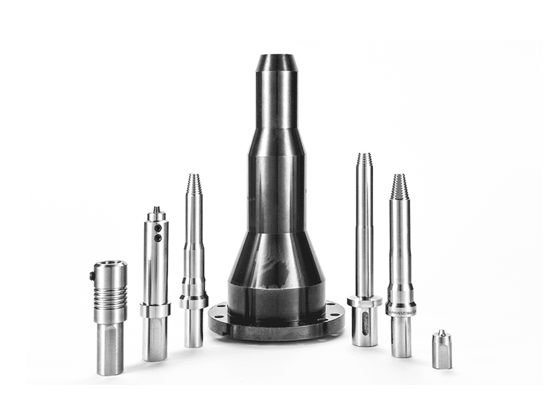
For closed-contour welds, the exit hole is another leak risk. A conventional FSW tool leaves a keyhole when the pin is withdrawn. In a circular coolant-channel cover, that keyhole can become a leakage point unless a secondary operation repairs it. Retractable-pin FSW eliminates the keyhole by gradually withdrawing the pin into the shoulder while the surrounding material is still plasticized, leaving a continuously filled seam.
Leak-tightness is verified at two levels: the weld must be sound, and the finished housing must pass the component leak test. Pressure decay, helium mass spectrometer testing, or specified IP-rating tests are common acceptance gates. The FSW process window should therefore be developed with the final leak-rate target in mind, not only tensile strength.
Tooling Strategy for Closed-Contour & Thin-Wall Welds
Tool selection changes the behavior of the weld. For e-motor housings and control boxes, the main candidates are conventional pin tools, retractable pin tools, and stationary-shoulder tools.
A conventional FSW tool is the standard choice for straight seams, open geometry, and thick enough sections where the keyhole can be cut off or placed outside the seal path. Retractable-pin tooling is preferred for circumferential covers, closed loops, and any geometry where a keyhole is not acceptable.
Stationary-shoulder FSW is especially useful for thin-wall control-box covers. Because the shoulder does not rotate with the pin, heat input is lower and surface overheating is reduced. That helps avoid thinning, flash formation, and distortion on 1–3 mm covers where flatness matters for gasket seating and lid assembly.
Bobbin tooling may be considered for hollow or double-sided access profiles, but it requires careful thickness control and is less common for thin e-motor covers than retractable-pin or stationary-shoulder solutions.
For closed-contour covers and circular housing seams, tool choice usually decides whether the seal is keyhole-free on the first pass. <AEE provides customer with optional features FSW tool> covers how pin-and-shoulder options are matched to e-drive component geometry.
Process Parameters & Heat-Input Control
FSW parameters are developed as a window, not a single fixed point. Rotation speed, travel speed, axial force, and tool tilt interact. For 6xxx aluminum housings, the main goal is to produce full material flow without overheating the heat-affected zone or creating flash.
Too much heat softens heat-treatable alloys and can leave the weld region under-strength. Too little heat produces cold lap, voids, or root flaws. The correct window depends on plate thickness, tool shoulder diameter, pin length, and joint design.
Thin-wall electric control boxes require tighter heat control than thick motor flanges. Overheating a 2 mm cover can cause burn-through or local thinning. A stationary-shoulder tool, reduced shoulder pressure, or faster travel speed may be used to keep heat input low while maintaining fill.
Process monitoring is important for sealed housings. Force, torque, spindle power, and temperature should be logged during welding. If a spindle load or force signature drifts outside the qualified window, the part can be flagged before it reaches final leak testing. This turns FSW from a standalone weld operation into a traceable production process.
Quality Control & Leak Verification
Sealed e-motor housings need a layered inspection approach. Visual testing catches surface flash, underfill, and exit-hole defects. Volumetric inspection such as X-ray can detect tunnels and voids. Ultrasonic or phased-array examination helps find tight root flaws and kissing-bond-type indications, although interpretation is more difficult than in fusion welds.
The weld procedure itself should be qualified in accordance with the ISO 25239 series, especially procedure specification and qualification [1] and quality and inspection requirements [2]. For e-drive programs with aircraft heritage or stringent structural requirements, AWS D17.3 is frequently referenced [3]. Visual testing follows ISO 17637 [4], and ultrasonic testing follows the general techniques described in ISO 17640 [5].
Destructive evaluation remains part of initial qualification. Tensile tests, bend tests, and polished cross-sections confirm the weld class before production begins. The final component leak test then verifies the entire sealing system: weld, cover plate, O-ring interface, and housing casting.
Production Planning & Machine Configuration
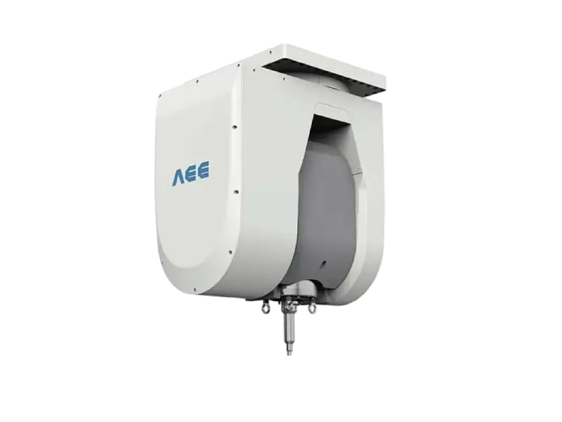
The best FSW machine for an e-motor housing depends on part size, weld path complexity, and required cycle time. A C-type machine works well for compact control boxes and small covers. A gantry-type gantry FSW machine accommodates larger battery trays, cooling plates, and long weld paths. A 3D FSW machine is selected when the joint is not planar and requires coordinated multi-axis movement.
Fixture design is just as important as the machine. The housing must be clamped with enough force to resist forging loads without crushing thin walls. Backing plates support the root side and help control heat. For housings with cast sections or curved profiles, the fixture may need custom supports to keep the joint in contact with the backing during the full weld length.
Automation options such as laser seam tracking, automatic loading, and force or position control help keep cycle time and process repeatability within specification. For high-volume EV programs, the welding cell should include part identification, parameter logging, and defect flagging so each housing can be traced back to its weld record.

For a feasibility review of your e-motor housing or electric control box, send a cross-section drawing, material and thickness, coolant-channel geometry, and target leak-rate or IP rating to [email protected] or call +86 18325808715. A short sample weld can confirm whether the seal path is weldable before you commit to full tooling.
Next Step: Send Your E-Motor Housing Drawing for Review
A productive FSW evaluation starts with the right input data. When preparing a feasibility request, include the following:
- 2D or 3D drawing of the housing and cover
- Aluminum alloy and temper
- Joint thickness and weld length
- Coolant-channel layout and seal-path requirements
- Target leak rate or IP rating
- Annual volume and current joining method
The review can then focus on joint design, tool selection, machine size, and whether a retractable-pin or stationary-shoulder tool is required. Contact [email protected] or +86 18325808715 with the above information to begin a sample-welding feasibility study.
FAQ
Is FSW suitable for thin-wall electric control box covers?
Yes. With stationary-shoulder tooling and controlled heat input, FSW can join thin-wall aluminum covers without burn-through. The key is developing a parameter window that maintains flow without overheating the cover.
Can FSW weld a closed circular coolant channel without leaving an exit hole?
Yes. Retractable-pin FSW gradually withdraws the pin into the shoulder, filling the exit area and producing a keyhole-free closed contour weld.
What aluminum alloys are used for e-motor housings and control boxes?
6xxx alloys such as 6061 and 6082 are common for machined housings, while 5xxx sheet is widely used for covers. Cast-to-wrought combinations can also be welded with FSW when the cast material is sound.
How do you verify leak-tightness after FSW?
Leak verification usually combines weld inspection with component testing. FSW welds may be checked visually, by X-ray or ultrasonic testing, and the finished housing is tested by pressure decay or helium leak testing according to the specified acceptance level.
Which FSW configuration is best for e-motor housings?
It depends on geometry. A C-type machine suits small covers, a gantry machine handles larger panels or multiple parts, and a 3D machine is used for curved or multi-plane weld paths. Tooling should be selected based on whether the weld loop is open or closed.
Does FSW require a backing plate for every housing weld?
Most housing welds require a backing plate or anvil to react the forging force and support the root side. Bobbin tooling can eliminate the need for rigid backing in some hollow profiles or self-reacting configurations, but it has thickness and access constraints.
References
[1] ISO 25239-4:2020, Friction stir welding — Aluminium — Part 4: Specification and qualification of welding procedures.
[2] ISO 25239-5:2020, Friction stir welding — Aluminium — Part 5: Quality and inspection requirements.
[3] AWS D17.3/D17.3M:2016, Specification for Friction Stir Welding of Aluminum Alloys for Aerospace Applications.
[4] ISO 17637:2016, Non-destructive testing of welds — Visual testing of fusion-welded joints.
[5] ISO 17640:2018, Non-destructive testing of welds — Ultrasonic testing — Techniques, testing levels, and assessment.
If you’re interested, check out these related articles:
AEE attend 13th International Symposium on FSW in Kyoto, Japan on 21 – 23 May 2024
AEE provides customer with optional features FSW tool