
Automated FSW Production Line for Aluminum Alloy Wheels: A Production Case Study
Table of Contents
- The Wheel Welding Problem: Why Fusion Welding Falls Short
- Line Overview and Process Envelope
- Automation Sequence: From QR Scan to Finished-Wheel Discharge
- Tooling Strategy: Keyhole-Free Welding with Retractable Pins
- Quality Assurance and Traceability
- Performance Outcomes and Practical Lessons
- Engineering Support for Automated Wheel Welding
- FAQ
- What is the maximum wheel diameter this FSW line can weld?
- How does it eliminate the FSW exit keyhole?
- What cycle time can the line achieve?
- What quality and traceability functions are included?
- Does the line require an operator for every wheel?
- References
The Wheel Welding Problem: Why Fusion Welding Falls Short
Aluminum alloy wheels are geometrically simple at first glance, but their circumferential weld path is much less forgiving than a straight butt joint. The wheel disc and rim must be clamped, positioned, and welded with consistent depth around the full diameter, and any exit hole or root flaw becomes a stress concentration on a safety-critical rotating part.
Friction stir welding (FSW) is a solid-state joining process in which a non-consumable rotating tool plasticizes and forges material below the melting point [1]. For aluminum wheels, this avoids the porosity, hot cracking, and distortion that frequently appear with fusion welding, but it also creates a new requirement: the production line must hold force, position, and tool depth accurately while the workpiece rotates.
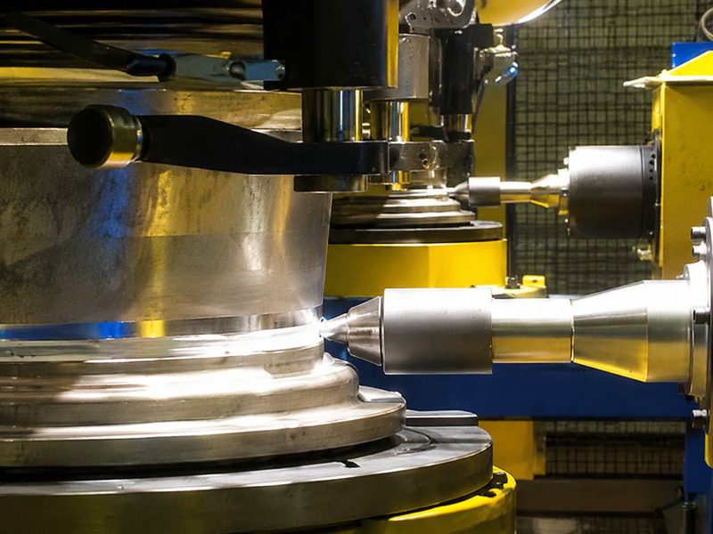
The case examined here is an automated FSW production line for aluminum alloy wheel components, designed around circumferential welding of wheel disc and rim structures for European automotive production. The line is built for 17–22 inch wheels with weld thickness from 1.2 mm to 10 mm, and it runs as an unmanned process from feeding to finished-part discharge.
Line Overview and Process Envelope
The wheel line centers on a dedicated Automatic FSW Production Line for Aluminum Alloy Wheel. Its core process parameters define what the machine can reliably weld:
| Parameter | Specification |
|---|---|
| Weld thickness | 1.2–10 mm |
| Wheel diameter | 17–22 in |
| Maximum welding speed | 2.5 m/min |
| Maximum spindle rotation | 6000 rpm |
| Cycle time | 45 JPH |
| Tooling | Retractable FSW tool, keyhole-free |
| Control | Constant pressure welding, laser tracking |
| Automation | QR code scanning, robot load/unload, automatic positioning |
The constant-pressure welding mode is important for wheel work because rotary clamping and rim runout can produce small local variations in part height. A purely position-controlled plunge may weld too shallow on one side and too deep on the other. Constant pressure allows the tool to follow the joint while maintaining the forging force required for sound material flow.
Automation Sequence: From QR Scan to Finished-Wheel Discharge
The line organizes the wheel operation into a closed-loop sequence rather than a collection of manual weld stations:
- QR code scanning reads the wheel variant before loading.
- Robot loading/unloading moves the wheel into the fixture without manual handling.
- Automatic feature identification and positioning locates the wheel disc and rim instead of relying on a fixed mechanical datum.
- Wheel disc and rim clamping secures the part for circumferential welding.
- Laser tracking follows the joint and supports welding start-point positioning.
- Constant-pressure FSW performs the circumferential weld with retractable tool exit.
- Welding quality judgement and discharge separates finished products from waste products automatically.
The specialized HMI works with a process database: operators input welding parameters for different part numbers, and the line executes automatic welding without re-teaching the full sequence for every wheel variant. That is the practical difference between a standalone FSW machine and a production line—variant changeover is part of the control system, not a manual setup event.
Tooling Strategy: Keyhole-Free Welding with Retractable Pins
A conventional FSW tool leaves an exit keyhole where the pin withdraws from the weld. For a closed circumferential weld, that keyhole would force secondary plug welding or machining, adding cost and creating potential failure risk.
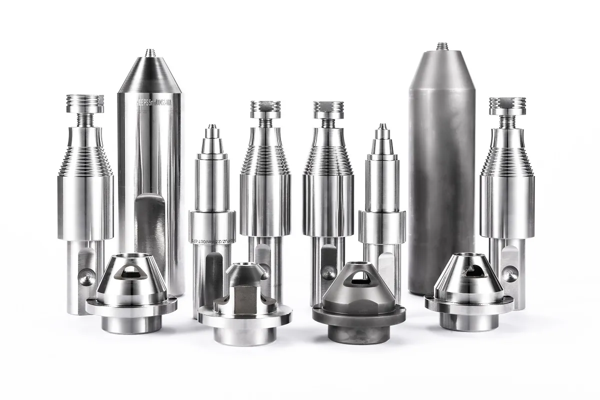
The wheel line uses a Retractable FSW Tool. The shoulder and pin move independently. As the weld closes around the circumference, the pin retracts gradually into the shoulder, allowing plasticized material to fill the exit region and produce a keyhole-free weld. This is essential for wheel rims because the weld path returns to its starting point; there is no convenient runoff tab.
Compared with a Conventional FSW Tool, the retractable design adds more moving components and requires precise pin-position control, but the benefit is direct: no exit hole, improved surface continuity, and less post-weld dressing.
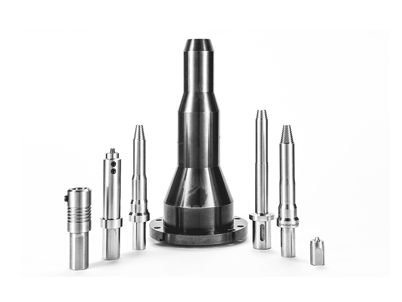
AEE also supplies optional features for pin tools, including geometry and material selection packages for difficult applications. <AEE provides customer with optional features FSW tool> covers pin geometry, shoulder features, and material selection for demanding welding tasks.
Quality Assurance and Traceability
Wheel production is not tolerant of intermittent defects. The line therefore records more than the weld motion: it monitors welding pressure, laser-tracked joint position, and quality judgement during the cycle.
For aluminum FSW, procedure qualification commonly follows ISO 25239 [1], while aerospace-grade aluminum practice is addressed by AWS D17.3/D17.3M [2]. In an automotive wheel line, production-scale traceability matters just as much as initial weld qualification. Modern manufacturing expects every part to be linked to its process parameters, variant QR code, and discharge classification [3].
The traceability system embedded in the wheel line allows the user to recall the welding record for a specific wheel, review pressure and tracking data, and separate conforming parts from non-conforming parts automatically. This reduces reliance on downstream inspection as the only quality filter.
If you are evaluating a similar wheel line, prepare a short technical brief with the rim material, weld depth, wheel diameter range, and target hourly output. Send it to [email protected] so the engineering team can confirm the appropriate spindle, clamping concept, and tooling configuration.
Performance Outcomes and Practical Lessons
The case line demonstrates several measurable outcomes that matter more than machine sales specifications:
- Unmanned operation: feeding, clamping, weld start-point location, FSW, finished part discharge, and waste part discharge occur without manual intervention.
- Keyhole-free circumferential welding: retractable pin technology removes the exit-hole defect and reduces post-weld rework.
- 45 JPH cycle performance: the line is organized around a repeatable wheel cycle rather than high-speed straight-line welding.
- Variant handling: QR-based wheel identification plus the HMI process database supports multiple wheel types on the same line.
- Quality integration: welding pressure display, laser tracking, start-point positioning, and final quality judgement are built into the line instead of being added as optional sensors.
The main engineering lesson is that wheel automation is dominated by part handling and process consistency, not by absolute welding speed. A 2.5 m/min circumferential weld is modest compared with long straight-profile FSW lines, but the challenge is maintaining that weld quality through clamping, rotation, and tool exit on every single wheel.
Engineering Support for Automated Wheel Welding
A wheel production line should not be specified from a catalog price alone. The correct configuration depends on wheel diameter range, rim joint design, aluminum alloy, target cycle time, and whether keyhole-free closure is mandatory.
For an engineering evaluation, AEE recommends providing the following with the first inquiry:
- Wheel or rim 2D/3D drawing and weld joint section
- Aluminum alloy grade and weld depth
- Minimum and maximum wheel diameter
- Required cycle time or hourly output
- Factory space, power, and compressed air availability
- Quality data and traceability requirements
Contact: [email protected]
Phone/WhatsApp: +86 18325808715
FAQ
What is the maximum wheel diameter this FSW line can weld?
The automated line is specified for wheel diameters from 17 inches to 22 inches, with weld thickness from 1.2 mm to 10 mm.
How does it eliminate the FSW exit keyhole?
The line uses a retractable FSW tool. The pin withdraws gradually into the shoulder while the plasticized material fills the exit region, producing a closed circumferential weld without a keyhole.
What cycle time can the line achieve?
The line is designed for a cycle rate of 45 JPH, although actual output depends on wheel joint length, material, weld depth, and part loading variation.
What quality and traceability functions are included?
The system includes welding pressure display, laser tracking, welding start-point positioning, QR code reading, and welding quality judgement. The HMI process database stores parameters for different wheel variants.
Does the line require an operator for every wheel?
No. The line supports unmanned operation from feeding, clamping, and welding through finished-product and waste-product discharge. Operators supervise the line and manage variant changeover through the HMI.
References
[1] ISO 25239:2020, Friction stir welding — Aluminium, International Organization for Standardization.
[2] AWS D17.3/D17.3M:2016, Specification for Friction Stir Welding of Aluminum Alloys for Aerospace Applications, American Welding Society.
[3] TWI Ltd., Friction Stir Welding (FSW) Technical Knowledge, The Welding Institute.
If you’re interested, check out these related articles:
AEE attend 13th International Symposium on FSW in Kyoto, Japan on 21 – 23 May 2024
Customized Dissimilar Material Welding Manufacturers in China