
Friction Stir Welding for Rocket & Launch Vehicle Structures: Process Guide
Table of Contents
- Why FSW Replaces Fusion Welding in Launch Vehicle Structures
- Materials and Joint Configurations in Rocket Structures
- Process Control for Aerospace-Grade FSW
- Machine Selection for Rocket and Launch Vehicle Structures
- Curved Shells, Domes, and Circumferential Welds
- Tooling for Launch Vehicle Structures
- Quality Assurance and Qualification
- Translate Your Weld Specification into a Validated FSW Cell
- Plan Your Launch-Vehicle FSW Line with AEE
- Frequently Asked Questions
- Can FSW weld 2219 and 2195 aluminum for cryogenic propellant tanks?
- What FSW machine configuration is best for curved rocket domes?
- How does FSW avoid exit holes in circumferential tank welds?
- What NDT methods are used to validate FSW welds on launch structures?
- Does FSW require post-weld heat treatment for aerospace aluminum?
- References
Rocket and launch vehicle structures push aluminum alloys into operating conditions where fusion welding often fails. 2xxx and 7xxx series alloys are crack sensitive, cryogenic tank walls must remain leak tight, and large curved panels can tolerate almost no post-weld distortion. Friction stir welding has become the preferred solid-state joining process for these applications because it welds below the melting point, preserves alloy strength, and produces repeatable full-penetration joints [1][2].
Why FSW Replaces Fusion Welding in Launch Vehicle Structures
Launch vehicle primary structures rely on aluminum alloys selected for high specific strength and cryogenic performance. Fusion welding of 2219, 2195, or 7075 aluminum can produce porosity, hot cracking, and severe distortion. FSW operates in the solid state below the melting range of the base material, so it avoids solidification defects and produces a fine-grained weld nugget with strength values close to the parent metal [2][4].
For rocket fuel tanks, interstage rings, and payload adapter structures, the process offers three practical advantages. First, full-penetration butt welds can be produced in long aluminum panels without filler wire or shielding gas. Second, distortion is low enough to reduce post-weld straightening and machining. Third, the process is repeatable once a qualified welding procedure specification is established under aerospace standards such as AWS D17.3/D17.3M and ISO 25239 [2][3].
Materials and Joint Configurations in Rocket Structures
Common launch vehicle alloys include 2219, 2195, and 7075 aluminum. 2219 and 2195 are frequently used for cryogenic propellant tanks because they retain toughness at low temperature. 7075 is used in structural rings and heavily loaded machined components. FSW supports butt, lap, and fillet-type configurations depending on the part design, but rocket structures most often use butt joints in skin-stringer panels, dome gore panels, and barrel sections.
Joint preparation for FSW is different from fusion welding. Tight fit-up, controlled clamping, and a rigid backing bar or self-reacting tool are required to resist the high axial forging forces generated during welding. For thin panels, the backing plate also controls thermal conduction and prevents root-side overheating.
Aerospace material choices often involve pairing different aluminum grades in one assembly. <Customized Dissimilar Material Welding Manufacturers in China> covers how tailored FSW process development supports dissimilar aluminum combinations in production.
Process Control for Aerospace-Grade FSW
Aerospace FSW requires more than setting spindle speed and travel speed. The main control variables are tool rotation speed, travel speed, axial force or plunge depth, tool tilt angle, and tool geometry. Instead of using fixed universal parameters, launch vehicle programs develop a qualified parameter window through design of experiments, macro-section inspection, and mechanical testing. The final parameter set is recorded in a welding procedure specification and supported by a procedure qualification record [2][3].
Machine capability determines how precisely these parameters are maintained during long weld runs. Force-controlled machines hold a constant axial force through thermal expansion and local thickness variation, which is important for large cylindrical structures. Position-controlled machines are simpler but can produce inconsistent weld quality if part stiffness changes along the seam. Aerospace FSW cells often combine force feedback, spindle torque monitoring, and real-time temperature data logging for traceability.
Machine Selection for Rocket and Launch Vehicle Structures
Launch vehicle components fall into three machine categories. Extra-length gantry machines weld long straight barrel and skin-stiffener seams. Heavy-load gantry machines weld thick dome transition rings and heavily loaded structural forgings. 3D FSW machines weld curved shells, dome segments, and complex profiled components.
For large aluminum panels and barrels, an Extra-length Straight Profile FSW Machine provides the long X-axis travel needed for rail-type longitudinal seams. A Gantry FSW Machine supports flat or slightly curved 2D weld paths and can be configured for wide panel work in battery trays and rocket barrel sections.
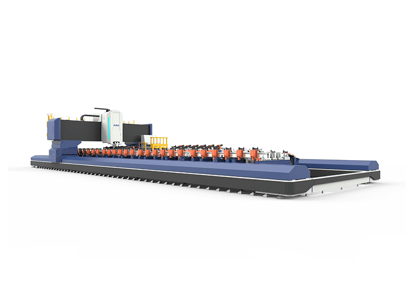
For thick aluminum sections such as forged rings and heavy tooling plates, a Heavy Load FSW Machine can deliver 200 kN maximum Z-axis force, 872 Nm spindle torque, and 105 kW spindle power. This class of machine supports single-side aluminum weld depths up to 100 mm and copper weld depths up to 35 mm, which covers most launch vehicle structural requirements.
Curved Shells, Domes, and Circumferential Welds
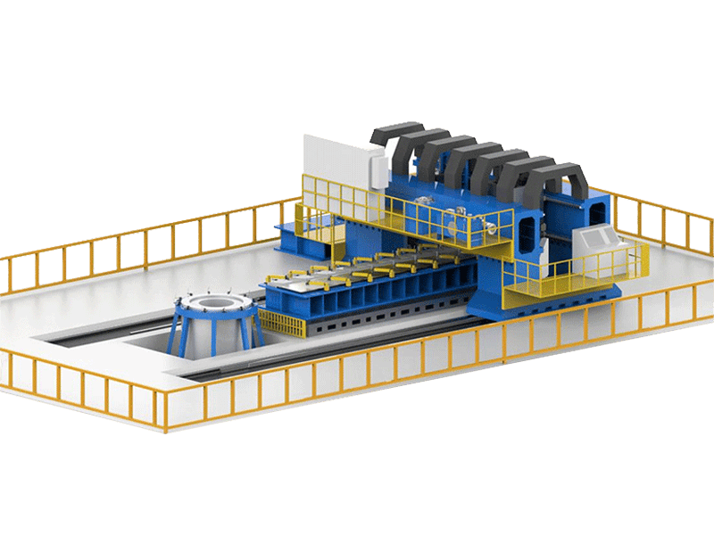
Propellant tank domes and interstage shells are not flat. They require multi-axis motion to keep the tool normal to the weld surface while maintaining constant travel speed. A 3D FSW Machine with an AC swing head can weld curved seams with the correct tool orientation and through-thickness force distribution. This is critical for dome gore panels and circumferential tank welds.
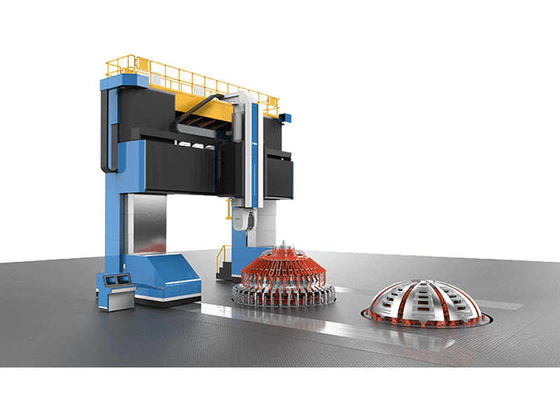
Circumferential welds on pressure vessels must close without leaving an exit hole. A Retractable FSW Tool gradually withdraws the pin into the shoulder at the end of the weld cycle, allowing plasticized material to fill the keyhole. This produces a fully sealed weld without a separate start-and-stop block or post-weld machining.
Tooling for Launch Vehicle Structures
Tool design drives material flow, heat generation, and weld quality in aerospace aluminum. Conventional single-piece pin tools are suitable for many long straight butt welds. Bobbin FSW Tool designs use upper and lower shoulders to weld without a rigid backing bar, which helps when access to the back side is limited. Stationary Shoulder FSW Tool designs separate the rotating pin from a sliding shoulder, reducing heat input, preventing flash, and improving surface finish on thin-wall and fillet-type rocket components.
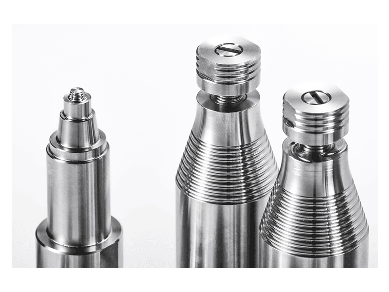
Tool material selection depends on the alloy family and weld length. Steel tools work for many aluminum applications, while high-temperature alloys and polycrystalline cubic boron nitride are used as material demands increase. Tool inspection and management should be integrated with weld parameter traceability to avoid pin wear becoming a hidden quality risk.
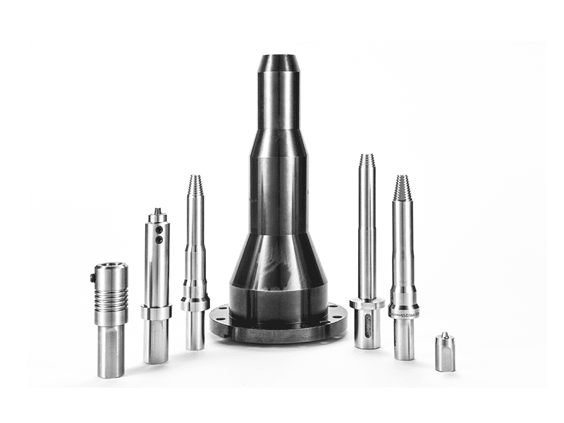
Tooling configuration choices determine whether a rocket fuel tank weld closes cleanly or needs costly rework. <AEE provides customer with optional features FSW tool> covers how optional tool features are specified for production FSW systems.
Quality Assurance and Qualification
Launch vehicle FSW welds are validated by non-destructive testing and mechanical testing. X-ray inspection detects volumetric defects such as tunnels and voids. Phased array ultrasonic testing detects lack-of-fusion, root flaws, and embedded defects in thick sections. Tensile, bend, and fatigue tests confirm that the joint meets design allowables. This qualification path is aligned with AWS D17.3/D17.3M and ISO 25239 requirements [2][3].
In production, each weld should be traceable to the machine, spindle, tool serial number, operator, and parameter record. Real-time force, torque, and temperature monitoring supports part-level conformity and allows root-cause analysis if NDT findings occur. This data-driven approach reduces the risk of batch rejection in launch vehicle programs.
Staying current with FSW process research and supplier capability helps aerospace buyers make better qualification decisions. <AEE attend 13th International Symposium on FSW in Kyoto, Japan on 21 – 23 May 2024> covers how AEE participates in the international FSW research community.
Translate Your Weld Specification into a Validated FSW Cell
If your team is developing a rocket tank dome, barrel weld, or interstage joint, the first step is defining the process window on representative test coupons. AEE supports sample welding, feasibility studies, and welding procedure development for launch vehicle alloys and configurations.
Contact AEE at [email protected] or +86 18325808715 with your alloy, thickness, weld length, curvature, and required NDT class. The engineering team can recommend the correct machine platform, tooling configuration, and process qualification path before you commit to capital equipment.
Plan Your Launch-Vehicle FSW Line with AEE
Aerospace Engineering Equipment (Suzhou) Co., Ltd. supplies turnkey FSW systems for global aerospace and launch vehicle manufacturers. To receive a technical proposal, provide the following information:
- Base alloy or alloys and weld thickness range
- Part dimensions and weld path geometry
- Required NDT and mechanical testing standards
- Target production rate or cycle time
- Facility constraints such as floor space and power supply
Email [email protected] or call +86 18325808715 to discuss your application with an FSW engineer.
Frequently Asked Questions
Can FSW weld 2219 and 2195 aluminum for cryogenic propellant tanks?
Yes. FSW is widely used for 2219 and 2195 aluminum cryogenic tanks because the solid-state process avoids solidification cracking and porosity associated with fusion welding of these alloys [1][2].
What FSW machine configuration is best for curved rocket domes?
A 3D FSW machine with a multi-axis swing head is preferred for curved dome and shell welds. It maintains constant tool orientation and forging force across changing surface angles.
How does FSW avoid exit holes in circumferential tank welds?
A retractable pin tool withdraws the pin into the shoulder at the end of the weld, allowing plasticized material to fill the keyhole. This creates a sealed circumferential weld with no exit hole.
What NDT methods are used to validate FSW welds on launch structures?
Common methods include X-ray inspection for volumetric defects, phased array ultrasonic testing for embedded defects and root flaws, and dye penetrant testing for surface-breaking indications [2][3].
Does FSW require post-weld heat treatment for aerospace aluminum?
Some aerospace alloys are used in the as-welded condition, while others require post-weld aging or stress relief depending on design allowables. The requirement is determined during procedure qualification and component design.
References
[1] TWI. Friction stir welding of aluminium alloys. Technical knowledge, TWI Ltd. https://www.twi-global.com/technical-knowledge/job-knowledge/friction-stir-welding-147/
[2] American Welding Society. AWS D17.3/D17.3M:2016, Specification for Friction Stir Welding of Aluminum Alloys for Aerospace Applications.
[3] ISO 25239-1:2020, Friction stir welding — Aluminium — Part 1: Vocabulary. International Organization for Standardization.
[4] Mishra, R.S., Ma, Z.Y. Friction stir welding and processing. Materials Science and Engineering: R: Reports, vol. 50, no. 1–2, 2005, pp. 1–78.
[5] Threadgill, P.L., Leonard, A.J., Shercliff, H.R., Withers, P.J. Friction stir welding of aluminium alloys. International Materials Reviews, vol. 54, no. 2, 2009, pp. 49–93.
If you’re interested, check out these related articles:
AEE attend 13th International Symposium on FSW in Kyoto, Japan on 21 – 23 May 2024
Refill Friction Stir Spot Welding (RFSSW)
Customized Dissimilar Material Welding Manufacturers in China