
FSW in Aerospace: Longitudinal and Circumferential Fuel Tank Seam Welding
Table of Contents
- Why Fuel Tank Seam Welding Is Different
- Longitudinal Seam Welding in Aerospace Fuel Tanks
- Circumferential Seam Welding for Domes and End Closures
- Material Considerations for Aerospace Fuel Tank Aluminum
- Machine Requirements for Long, Reproducible Seam Welds
- Defect Prevention and Process Control
- Qualification, Inspection, and Documentation
- Start Your Aerospace FSW Qualification with a Production-Ready Partner
- Frequently Asked Questions About FSW Fuel Tank Seam Welding
- What is the difference between longitudinal and circumferential FSW seam welding?
- Can FSW weld both thin and thick aerospace fuel tank walls?
- Why is keyhole elimination important for circumferential tank welds?
- Which FSW machines are suitable for large aerospace fuel tank seams?
- What standards apply to aerospace FSW fuel tank welding?
- References
Fuel tanks present one of the most unforgiving joining challenges in aerospace manufacturing. The weld must contain fuel or pressurant, survive vibration and thermal cycling, and remain inspectable along long closed seams. Friction stir welding (FSW) has become the preferred process for many aluminum fuel tank programs because it is a solid-state joining method that operates below the melting point of the base material [1]. This avoids the solidification defects that complicate fusion welding and helps preserve joint strength in heat-treatable aluminum alloys.
The geometry of a fuel tank generally creates two seam types. Longitudinal seams run along the barrel or panel axis, joining rolled plate, formed sheet, or extruded profiles. Circumferential seams close the ends, joining domes, end caps, bosses, and cylindrical sections. Both seam types demand tight process control, but they place different requirements on fixturing, machine axes, and tooling.
Why Fuel Tank Seam Welding Is Different
Fuel tank welds are pressure boundaries. Unlike a cosmetic or non-critical structural weld, a tank seam has no redundant load path and no acceptable leak. The weld must combine strength, ductility, fatigue resistance, and seal integrity. FSW fits this requirement because the stirred joint is formed without melting, which reduces porosity, hydrogen cracking, and hot tearing [1].
Aerospace programs also require formal qualification. In the United States, AWS D17.3/D17.3M provides requirements for friction stir welding of aluminum alloys in aerospace applications [2]. International programs often reference ISO 25239 for aluminum FSW [3]. These standards drive weld procedure specification, operator qualification, destructive testing, and nondestructive inspection. A fuel tank seam, therefore, is not just a weld; it is a qualified, documented, and repeatable manufacturing process.
Longitudinal Seam Welding in Aerospace Fuel Tanks
Longitudinal seams run along the main length of a tank. In many designs, a flat plate is rolled or formed into a cylinder, and the longitudinal seam closes the barrel. In other cases, multiple extruded panels are joined edge to edge to create wide tank walls or integral stiffened structures.
The primary challenge in longitudinal welding is maintaining consistent tool engagement over a long weld length. The machine must hold accurate position or force control while the fixture resists thermal expansion and clamping loads. A gantry or heavy-load FSW platform with a long X-axis stroke is often selected for this work.
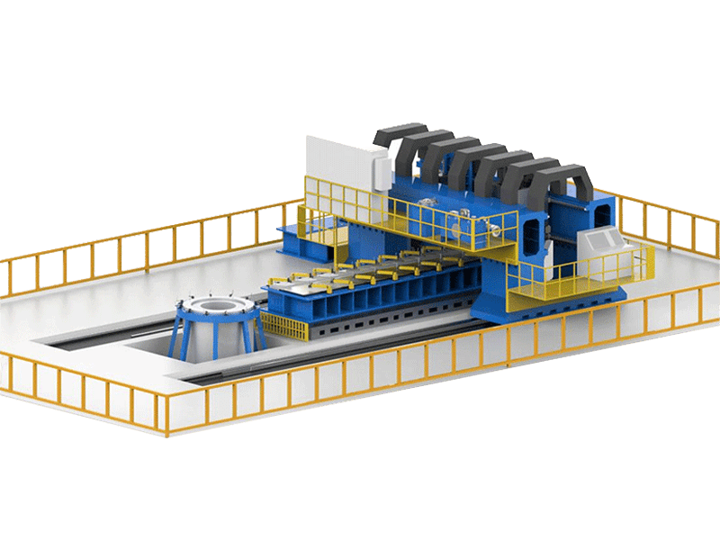
For closed or semi-closed hollow sections, a self-reacting bobbin FSW tool can weld the seam from both sides without requiring rigid backing support inside the cavity. This is especially useful for barrel-style tanks where internal backing access is limited.
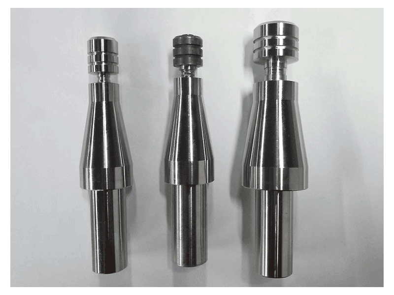
Longitudinal seams also benefit from continuous force and temperature monitoring. Because the seam is straight, automation is straightforward: a single pass can cover the full length, and laser tracking or tool-set point detection can confirm start position before each weld.
Circumferential Seam Welding for Domes and End Closures
Circumferential seams close the tank. They join a dome or end cap to the cylindrical section, attach bosses or ports, or connect multiple cylindrical segments. Unlike a straight longitudinal seam, a circumferential weld is a closed-loop path. The tool returns to its starting point, which makes weld termination and keyhole control a central issue.
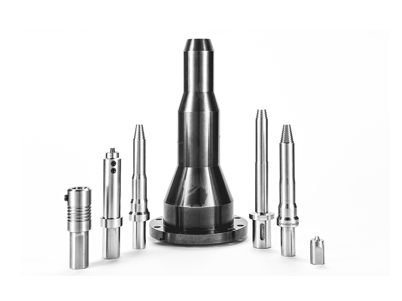
A retractable FSW tool addresses this by gradually retracting the pin into the shoulder at the end of the weld. The plasticized material fills the exit region, producing a fully closed weld without a keyhole. This is particularly valuable for fuel tanks because any keyhole becomes a potential leak path and a point of stress concentration.
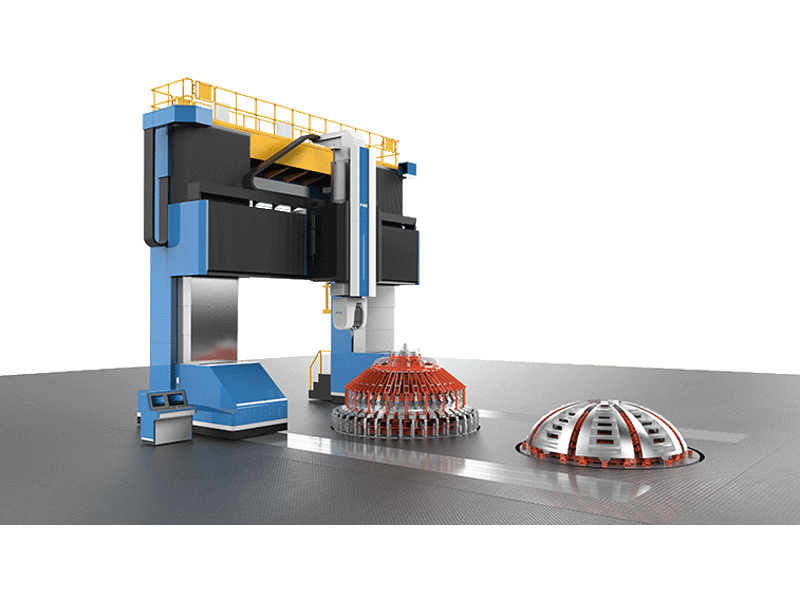
Circumferential welding requires coordinated rotary motion. A C-axis, rotary table, or positioner must maintain constant surface speed and consistent tool tilt as the part rotates. A 3D FSW machine supports curved and spatially oriented seams, but many cylindrical tank closures can be welded with a heavy-load platform equipped with a rotational axis. The key is not motion alone; it is keeping the tool’s axial force and orientation stable through the full 360-degree path.
Material Considerations for Aerospace Fuel Tank Aluminum
Many aerospace fuel tanks use heat-treatable aluminum alloys in the 2xxx, 6xxx, and 7xxx series. These alloys offer high specific strength, but several are difficult to fusion weld without hot cracking or joint softening. FSW is attractive because the lower heat input and solid-state mechanism limit these problems [1].
Alloy-specific procedure development still matters. Tool rotation speed, travel speed, axial force, and shoulder geometry must match the alloy’s hot workability and the required post-weld properties. Some fuel tank designs require post-weld inspection in the as-welded condition, while others allow re-heat-treatment. The weld procedure must define these conditions clearly.
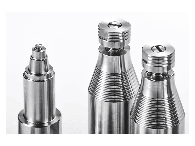
A stationary shoulder FSW tool can reduce heat input and improve surface finish, which is beneficial when distortion control and surface quality are critical. The stationary shoulder limits flash and produces a more uniform thermal gradient through the thickness, valuable for thin-wall tank structures.
Machine Requirements for Long, Reproducible Seam Welds
Fuel tank seam welding does not tolerate machine deflection. The FSW head must maintain its set depth and lateral position while the fixture and part heat up. Machine stiffness, spindle torque, and Z-axis force capacity all matter. A heavy-load platform with strong gantry or C-frame construction provides the rigidity needed for thick aluminum walls and long weld lengths.
Spindle selection is equally important. Higher-torque spindles support thicker sections and stronger alloys, while lower-power spindles may suit thin sheet. The friction stir welding spindle series includes models matched to different weld depths and materials.
Force control or position control may be used depending on part tolerance. Force control can compensate for slight thickness variation, while position control may be preferred for precisely machined components. Many aerospace programs specify force, torque, and temperature logging so every weld is traceable.
Aerospace fuel tank tooling also tends to be application-specific. Tank programs often require special shoulder geometry, pin dimensions, cooling channels, or tool holder features to match a specific joint configuration.
Aerospace fuel tank tooling often requires machine-specific optional features rather than a universal setup. <AEE provides customer with optional features FSW tool> covers how optional tool configurations support customer-specific welding requirements.
Defect Prevention and Process Control
The most serious FSW defects for fuel tanks are those that compromise pressure integrity: root lack-of-penetration, tunnel voids, wormholes, and internal cavities. Surface flash may not directly leak, but it can indicate improper shoulder engagement or excessive heat input.
Prevention starts before welding. The joint must be clean, aligned, and clamped close to the weld line. Gap tolerance must be controlled, and backing support must remain solid. During welding, process monitoring should capture spindle torque, axial force, temperature, and travel speed. A deviation from the validated parameter band is easier to catch in real time than after the tank enters final inspection.
After welding, inspectors look for both surface and subsurface indications. Visual inspection and dye penetrant testing can find surface-breaking defects. Radiographic testing and phased-array ultrasonic testing are used for internal discontinuities. For fuel tanks, final pressure testing or helium leak testing provides direct proof that the seam can hold the required fluid or gas.
Qualification, Inspection, and Documentation
A qualified FSW procedure is the foundation of a fuel tank seam welding program. ISO 25239-4 describes the specification and qualification of welding procedures for aluminum FSW [4]. The qualification record typically includes tensile tests, bend or macro tests, hardness surveys, and nondestructive inspection of test coupons. The procedure also defines essential variables such as tool geometry, rotation speed, travel speed, axial force, and any post-weld treatment.
Aerospace quality systems add another layer. EN 9100 establishes quality management requirements for aviation, space, and defense organizations [5]. Under this framework, machine calibration records, tool inspection data, material certifications, and operator training records are part of the weld package.
Aerospace fuel tank programs often rely on continuous technical exchange and process validation before production release. <AEE attend 13th International Symposium on FSW in Kyoto, Japan on 21 – 23 May 2024> covers international FSW research exchange on advanced aluminum joining topics relevant to structural aerospace applications.
This is the stage where specification should become implementation. Send your tank drawing, weld length, wall thickness, and target inspection standard to [email protected] for a technical recommendation on machine, fixture, and tooling configuration.
Start Your Aerospace FSW Qualification with a Production-Ready Partner
Fuel tank seam welding rewards a systematic approach: define the pressure boundary and material condition, design the fixture, select the correct machine and tool, qualify the procedure, and then lock the process with monitoring and traceability. Aerospace Engineering Equipment (Suzhou) Co., Ltd. supplies FSW machines, tooling, and turnkey process support for demanding aluminum structures, including long seam and circumferential applications.
Contact [email protected] or call +86 18325808715 to discuss a sample weld program, machine selection, or full production line for aerospace fuel tank components.
Frequently Asked Questions About FSW Fuel Tank Seam Welding
What is the difference between longitudinal and circumferential FSW seam welding?
Longitudinal FSW follows the tank axis in a straight or gently curved path, while circumferential FSW follows a closed circular path around the tank diameter. Circumferential welds require coordinated rotation and often use retractable tools to eliminate the exit keyhole.
Can FSW weld both thin and thick aerospace fuel tank walls?
Yes. The process is used across a wide thickness range, but machine size, spindle torque, and fixture design must be matched to the wall thickness. Thin sections require low heat input and tight fixturing, while thick sections require high Z-axis force and a rigid machine bed.
Why is keyhole elimination important for circumferential tank welds?
A closed circumferential seam returns to the starting point, which can leave a keyhole if a fixed-pin tool simply withdraws. Retractable FSW tools fill the exit region as the pin retracts, avoiding a leak path and reducing post-weld machining.
Which FSW machines are suitable for large aerospace fuel tank seams?
Longitudinal seams are commonly welded on gantry or heavy-load platforms with long X-axis strokes. Circumferential seams need a rotary axis or positioner. For complex dome profiles, a 3D FSW machine may be used. The best platform depends on tank diameter, weld length, wall thickness, and part access.
What standards apply to aerospace FSW fuel tank welding?
AWS D17.3/D17.3M covers FSW of aluminum alloys for aerospace applications [2]. ISO 25239 provides internationally recognized aluminum FSW requirements [3], and ISO 25239-4 addresses procedure qualification [4]. Aerospace quality systems typically follow EN 9100 [5].
References
[1] W. M. Thomas et al., “Friction Stir Butt Welding,” International Patent Application PCT/GB92/02203, Dec. 1991.
[2] AWS D17.3/D17.3M, Specification for Friction Stir Welding of Aluminum Alloys for Aerospace Applications, American Welding Society.
[3] ISO 25239-1:2020, Friction stir welding — Aluminium — Part 1: Vocabulary.
[4] ISO 25239-4:2020, Friction stir welding — Aluminium — Part 4: Specification and qualification of welding procedures.
[5] EN 9100:2018, Quality Management Systems — Requirements for Aviation, Space and Defense Organizations.
If you’re interested, check out these related articles:
Customized Dissimilar Material Welding Manufacturers in China
AEE attend 13th International Symposium on FSW in Kyoto, Japan on 21 – 23 May 2024
AEE provides customer with optional features FSW tool