
EV Liquid Cooling Plates: Why FSW Beats Brazing
Table of Contents
- Where Do Brazed Liquid Cooling Plates Fail?
- How Does FSW Create Leak-Free Liquid Cooling Plates?
- How Does FSW Avoid Leak Paths Without Filler?
- What Wall Thickness Works for FSW Cooling Plates?
- Why Does FSW Reduce Liquid Cooling Plate Manufacturing Cost at EV Volumes?
- What Should Buyers Verify Before Specifying an FSW Liquid Cooling Plate Line?
- Which Machine Type Fits Cooling Plate Production?
- How Can You Move a Liquid Cooling Plate Design Into an FSW Validation Run?
- What Questions Do EV Engineers Ask About FSW Liquid Cooling Plates?
- Does FSW work on all aluminum cooling plate alloys?
- Is there a minimum wall thickness for FSW?
- Can FSW seal the entire channel perimeter without an exit hole?
- What leak test should an FSW liquid cooling plate meet?
Electric vehicle liquid cooling plates need sealed internal channels that remain leak-tight through years of thermal cycling, vibration, and pressure loading. Friction stir welding is now the stronger production route because it removes two recurring failure mechanisms in vacuum brazed plates: flux entrapment and uncontrolled voiding. A brazed plate can pass initial leak testing and still open after repeated thermal expansion, while a solid-state FSW joint does not depend on a lower-melting filler layer that becomes the weak point. The comparison below explains where brazing falls short, how FSW changes the sealed-channel equation, and what buyers should confirm before committing to a liquid cooling plate production line.
Where Do Brazed Liquid Cooling Plates Fail?
Vacuum brazing joins an aluminum cover to a channel plate with a filler alloy that melts below the parent metal temperature. The whole assembly sits inside a furnace at high temperature while vacuum pulls air out of the joint. That furnace-level heating produces distortion, and the filler layer itself has different ductility and corrosion behavior from the parent material. After enough thermal cycles, the joint can crack near inlet bosses, outlet ports, or the plate edge where the cover is thinnest.
Inside the channel, flux residue and oxide pockets can block flow paths. A small void that passes a dry-air test can still fail a helium leak test because helium molecules are much smaller. Brazing also leaves a cast filler microstructure that behaves differently from the parent aluminum. In process reviews, we often see brazed plates that look acceptable after visual inspection but leak after thermal cycling, not because the brazing operator made a mistake but because the failure mode is built into the filler joint.
How Does FSW Create Leak-Free Liquid Cooling Plates?
Friction stir welding creates the joint by plasticizing aluminum instead of melting it. A rotating pin enters the seam between the channel plate and the cover. Friction heats the metal to a soft condition below the solidus temperature, and the pin forges the two surfaces together under axial force. The result is one continuous solid-state bond with no filler layer, no flux residue, and no capillary gap. For a liquid cooling plate, that removes the main leak paths vacuum brazing can introduce.
Because the process does not melt the base metal, the joint keeps most of the parent material strength. In 6xxx aluminum plates, the weld zone is usually stronger than the surrounding annealed channel wall. The heat-affected zone stays narrow, and the plate remains flat enough for the next assembly step. In our process work on water cooling plates, clamp rigidity and a stable tool shoulder predict a leak-tight result more reliably than raw spindle speed.
How Does FSW Avoid Leak Paths Without Filler?
Vacuum brazing fills the joint gap with a filler alloy that must wet both surfaces. If wetting is incomplete or flux becomes trapped, the joint has a void or a capillary path. FSW uses no gap-filling mechanism. The pin physically stirs the two aluminum faces together while the shoulder applies downward pressure, and the reconsolidated metal forms one bonded zone. There is no separate material layer to become a leak path.
What Wall Thickness Works for FSW Cooling Plates?
Most EV liquid cooling plates measure between 1 mm and 4 mm in the weld area, which sits well within the range of standard C-type and gantry FSW machines. Our C-type equipment is rated for welding thickness up to 8 mm, so it covers stamped or machined channel plates. Thin covers below 1 mm require tighter fixture support and lower heat input, and a stationary shoulder tool reduces surface flash. The limiting factor is usually not the FSW process but the flatness of the stamped cover before welding.
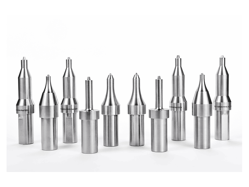
Tool geometry determines how material moves around the channel root, and the pin profile is part of the process development rather than a catalog choice. <AEE provides customer with optional features FSW tool> covers how optional tool features are matched to sealed-plate applications.
| Factor | Vacuum brazing | Friction stir welding |
|---|---|---|
| Leak path risk | Capillary joints, voids, and flux residue | Continuous solid-state joint |
| Distortion | Furnace-level heating of the whole part | Localized heating at the weld line |
| Filler and flux | Required | None |
| Post-process cleaning | Usually required | Not required for FSW |
| Joint strength | Filler alloy strength | Parent metal strength |
Why Does FSW Reduce Liquid Cooling Plate Manufacturing Cost at EV Volumes?
At EV production volumes, the cost difference shows up in the process sequence more than in the machine price. Vacuum brazing needs a batch furnace, pump-down time, brazing sheet or paste, and post-braze cleaning to remove flux. The entire part reaches brazing temperature, which increases distortion and scrap. FSW completes the weld in a single pass at room temperature with no consumables beyond the tool and no post-weld cleaning. The plate cycle becomes predictable, and the line can be automated around it.
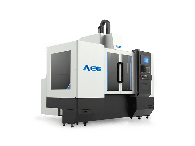
For high-mix plate designs, dual-worktable FSW machines reduce loading idle time because the operator loads one table while the spindle welds on the other. The AEE dual-worktable C-type machine uses a Siemens SINUMERIK 828D controller for four-axis linkage and automatic tool changing, so the same cell can handle different plate sizes without a long changeover. Automation is easier to implement than with a furnace because every operation occurs in the machine rather than in a separate batch process.
If your cooling plate program has channels that run close to the part edge or include complex port bosses, it is worth confirming the clamping span and shoulder clearance before you lock the bill of materials. Send your part drawing and target volume to [email protected] and we will confirm whether the channel geometry is FSW-friendly.
What Should Buyers Verify Before Specifying an FSW Liquid Cooling Plate Line?
The first check is the weld path. A liquid cooling plate usually needs a closed or multi-pass channel path around the perimeter. The machine must follow that path while holding tool tilt and axial force. We ask customers to send a 3D model before buying, because the path geometry decides whether a standard C-type machine is enough or a larger gantry machine with 2D servo angle control is needed. The drawing also shows whether an exit hole will occur and whether a retractable FSW tool should be used.
The second check is fixture behavior. FSW applies high axial force, and the plate must be clamped flat enough that the root does not buckle. A poorly supported channel plate will produce lack of penetration or flash. Buyers should ask for a sample welding run on their own material, not on a generic coupon, because the stamping springback and channel geometry affect how the plate sits under the tool. The third check is data logging. Force, torque, position, and temperature should be recorded for every plate, not just during process development.
Which Machine Type Fits Cooling Plate Production?
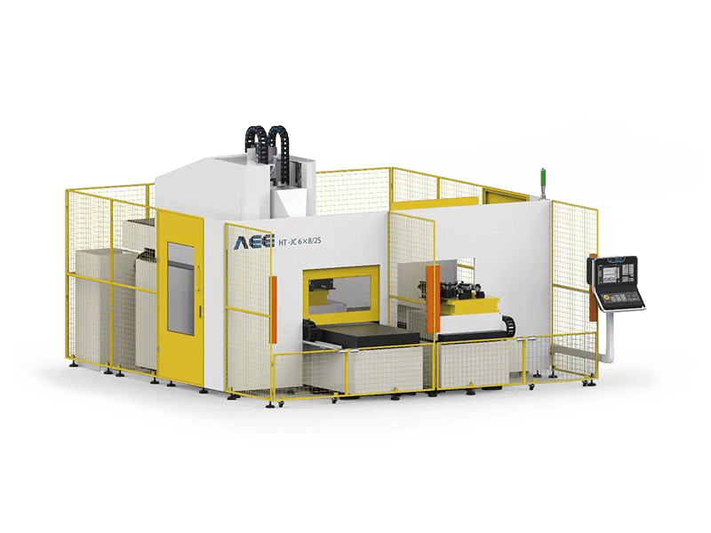
Small and medium plates can run on a C-type or dual-worktable C-type machine. Larger plates, including multi-board or integrated battery tray cold plates, are better handled on a gantry FSW machine because the workpiece stays stationary while the head travels over it. For closed contours, a retractable pin tool removes the exit hole. For thin covers with a cosmetic requirement, a stationary shoulder tool reduces flash and surface marking. The machine selection follows plate geometry first, then volume.

If the plate has dissimilar material inserts or a boss that cannot be welded in a straight line, the process route changes and the supplier’s experience with non-standard joints becomes the deciding factor. <Customized Dissimilar Material Welding Manufacturers in China> covers how Chinese FSW suppliers adapt tooling and fixtures for mixed-material thermal components.
How Can You Move a Liquid Cooling Plate Design Into an FSW Validation Run?
Locking in a cooling plate process is not a machine purchase decision first. It is a process decision. The wrong welding route shows up late as leak test failures, thermal cycling cracks, or a line that cannot hold cycle time. FSW removes the filler and flux variables, but the remaining variables are tool geometry, fixture stiffness, path control, and leak test criteria. Aerospace Engineering Equipment (Suzhou) runs feasibility studies on actual customer parts before a buyer commits to equipment or a turnkey line. Send your 3D drawing, channel cross-section, and target volume to [email protected] or call +86 18325808715. We will confirm the weld path, the recommended machine configuration, and the expected cycle time for your plate.
What Questions Do EV Engineers Ask About FSW Liquid Cooling Plates?
Does FSW work on all aluminum cooling plate alloys?
Most 3xxx, 5xxx, and 6xxx plate alloys weld well with FSW. The process is less alloy-sensitive than fusion welding because no solidification cracking occurs. 6xxx alloys are common for cooling plates because they balance thermal conductivity, formability, and strength. Dissimilar aluminum grades also work if the tool is specified for the material mix and the shoulder geometry matches the thinner member. The material condition matters more than the alloy family; a fully annealed cover may require different tool geometry than a work-hardened cover.
Is there a minimum wall thickness for FSW?
A common wrong assumption is that FSW needs a thick wall to avoid burn-through. In practice, most channel walls from 1 mm upward are weldable with the right clamping and a low heat input tool. Thinner covers below 1 mm may require a stationary shoulder tool and a rigid backing plate. The wall thickness at the weld line matters more than the overall plate thickness. If the channel root is unsupported, the bottom can bulge into the channel even on a thicker plate.
Can FSW seal the entire channel perimeter without an exit hole?
It depends on the plate shape and where the weld ends. For straight and simple curved channels, a standard single-shoulder tool may leave an exit hole at the end of the weld. If the exit hole falls inside the sealing envelope, the hole must be removed. A retractable pin tool withdraws the pin gradually and reconsolidates the material to close the hole. For open contours where the exit hole sits outside the sealed area, a conventional tool is usually sufficient.
What leak test should an FSW liquid cooling plate meet?
In cooling plate programs we have welded, buyers usually start with a dry-air pressure test and then move to helium leak testing for production control. Helium testing finds leaks that an air pressure test will miss at the same pressure because helium molecules are much smaller. The correct leak test depends on the vehicle-level requirement and where the plate sits in the battery system. Set the test pressure, temperature, and allowable leak rate before welding trials begin, not after. If your program needs compliance documentation for a specific leak test standard, send your specification to [email protected] and we will confirm what the FSW process can hold.
If you’re interested, check out these related articles:
Customized Dissimilar Material Welding Manufacturers in China
AEE attend 13th International Symposium on FSW in Kyoto, Japan on 21 – 23 May 2024