
Cast Aluminum FSW: Pre-Treatment Steps for Porosity Control
Table of Contents
- Porosity Sources in Cast Aluminum FSW
- Pre-Treatment Methods That Reduce Weld Porosity
- Why High-Pressure Die Castings Need Different Handling
- Parameter Adjustments for Cast Aluminum Welds
- Tooling and Machine Selection for Cast Aluminum
- Qualifying a Cast Aluminum FSW Process Before Production
- What Does a Cast Aluminum FSW Qualification Include?
- Common Questions About FSW of Cast Aluminum
- Does FSW eliminate porosity in cast aluminum?
- Can high-pressure die castings be friction stir welded?
- What is the best pre-treatment for cast aluminum before FSW?
- How do you inspect FSW of cast aluminum for porosity?
Friction stir welding cast aluminum depends more on what happens before welding than on the weld parameters themselves. In cast aluminum programs, the two questions that decide process stability are how much porosity already exists and how the casting was prepared. Most published guidance concentrates on rotation speed and travel speed. That focus misses the larger issue: a casting with surface oxide layers, absorbed moisture, or gas porosity cannot be rescued by parameter changes alone. This article covers pore sources, pre-treatment methods, parameter adjustments, tooling choices, and the qualification steps that make cast aluminum FSW production ready.
Porosity Sources in Cast Aluminum FSW
Cast aluminum is not a single material condition. In sand castings, slow solidification creates large shrinkage pores, coarse secondary phases, and possible sand inclusions near the surface. Permanent mold castings produce a finer porosity distribution but still contain oxide films from metal transfer. High-pressure die castings carry another risk: high-speed cavity fill traps gas and oxide skins, which can remain as sub-surface defects even when the outside of the casting looks acceptable.
Friction stir welding does not melt the base material, so it cannot simply float gas bubbles to the surface. The tool plasticizes a narrow band and forges it under pressure. Pre-existing voids inside the stir zone may collapse, but pores just outside the stir zone remain in the heat-affected zone. Large oxide films are worse. They become entrained as planar defects and can create root flaws or tunnel defects if the material cannot consolidate behind the pin.
I have reviewed cast aluminum weld trials where the macro section showed a clean nugget but an unchanged pore field only 3 mm from the weld boundary. That condition passes visual inspection and fails functional testing if the part is pressure-tested or fatigue loaded. The conclusion is not that FSW is unsuitable for cast aluminum. It is that the pore population must be measured and controlled before welding begins.
Pre-Treatment Methods That Reduce Weld Porosity
Pre-treatment decisions should follow the casting process, not a generic cleaning checklist. A sand casting with a rough as-cast skin needs different work than a machined permanent mold part. The table below separates the common methods by their actual function.
| Pre-treatment method | Primary effect | Best fit | Limits |
|---|---|---|---|
| Degassing or hot isostatic pressing | Closes internal shrinkage porosity | Sand and permanent mold castings with deep shrinkage | Does not repair surface-connected pores |
| Solution and aging heat treatment | Alters precipitate distribution and may round some pores | Heat-treatable Al-Si-Mg and Al-Cu cast alloys | Does not remove gas porosity already present |
| Machining the weld path | Removes oxide skin, sand grains, and mold coating | All castings, especially sand castings | Cutting must be dry and free of lubricant residue |
| Solvent degrease and drying | Removes oil, moisture, and loose debris | All castings before welding | Surface oxide can re-form quickly in humid plants |
| Surface oxide removal | Removes thick oxide film before tool entry | Castings with long storage or outdoor exposure | Use stainless steel brushes only |
Why High-Pressure Die Castings Need Different Handling
High-pressure die castings sit in a separate category. Skin layers and entrapped gas from high-speed fill do not respond to heat treatment the way shrinkage porosity does. If the weld path passes through a band of trapped gas, the resulting linear defect may appear intermittently along the seam. In these parts, the pre-treatment sequence often includes radiographic mapping first, then machining the weld path, then drying immediately before welding. The mapping step matters because it tells you whether a defect is inside the stir zone or outside it.
If your program involves cast aluminum with existing porosity or machined sealing surfaces, it is worth confirming the pre-treatment sequence and tooling interaction before finalizing your production plan. Send your casting material specification and weld area drawing to [email protected].
Parameter Adjustments for Cast Aluminum Welds
Once the casting is prepared, parameter selection becomes a matter of controlling heat and forging pressure without pushing the material beyond its narrow window. Cast aluminum alloys such as A356 or 319 often contain more silicon than wrought 6061. That silicon raises the abrasive load on the tool and changes how the material flows under the shoulder. A parameter set transferred directly from a wrought aluminum procedure commonly fails because the as-cast microstructure consolidates differently.
The first adjustment is travel speed. For castings with verified low porosity, a higher travel speed can still produce a sound joint. For castings with scattered porosity, slower travel speed gives the tool more revolutions per millimeter and gives the plasticized material more time to fill voids in the stir zone. The trade-off is heat: too slow creates flash, excessive softening, and a wider heat-affected zone. Watch the spindle torque and Z-axis force traces. A stable force curve with small variation usually indicates the tool is forging a consistent volume. A falling force curve at constant plunge can indicate the tool has entered a pore cluster or a soft zone.
I prefer force control for cast aluminum because it lets the shoulder maintain forging pressure when the tool passes through a pore field. Position control is simpler, but it can leave localized low-pressure regions exactly where the defect risk is highest. On a rigid machine with a responsive Z-axis, force control converts that variation into a small axial movement instead of a weld defect.
Tooling and Machine Selection for Cast Aluminum
Cast aluminum is harder on FSW tools than most wrought alloys. The silicon particles that give castings their fluidity act as a fine abrasive. A pin profile developed for 6061 may lose its features early when it runs through high-silicon cast material. Tool wear often shows up first as reduced thread depth on the pin, then as a gradual increase in spindle torque and a loss of material flow around the pin tip. Checking pin geometry after a short trial is a cheaper control than waiting for a production tool to fail.
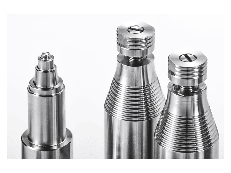
Stationary shoulder tooling is one option I evaluate for cast aluminum because it delivers lower heat input and leaves a flatter surface with less flash. The stationary shoulder slides on the workpiece while the pin rotates, which reduces thermal damage at the material surface. For castings with thin walls or a machined cosmetic surface, that difference matters. The tool range we specify includes cast aluminum alloy among the applicable materials for stationary shoulder FSW tooling.
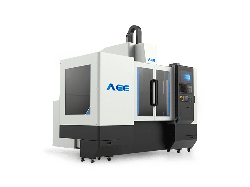
Machine selection follows the same logic. A cast component with subsurface porosity will expose any lack of bed stiffness or Z-axis control. If the machine cannot hold force steady while the tool crosses a pore cluster, the resulting weld will vary in quality even if the average parameters look correct. For thick cast sections, the machine must have enough torque and downforce to maintain full-depth consolidation. That is not a place to reduce the machine specification.
Tool features are normally fixed in a catalog, but cast aluminum programs often expose limits in tool design that generic tooling does not address. <AEE provides customer with optional features FSW tool> covers how optional tooling features such as customized pin profiles and shoulder geometries are specified for difficult materials.
Qualifying a Cast Aluminum FSW Process Before Production
Qualification for cast aluminum is not the same as copying a parameter sheet from a wrought alloy program. Because the incoming material condition varies from batch to batch, qualification has to include material verification, pre-treatment control, and destructive sectioning before any production order is released.
What Does a Cast Aluminum FSW Qualification Include?
The sequence I use starts with the worst-case casting, not the best-case sample:
- Select a casting from the highest-porosity area of the lot.
- Apply the planned pre-treatment exactly as production will run it.
- Run a weld coupon and record spindle torque, Z-axis force, and travel speed.
- Section the weld at three planes: entry, center, and exit.
- Map the remaining pores against the drawing requirements for pressure or fatigue.
- Repeat the trial on the production fixture to separate tool behavior from fixture behavior.
This sequence does two things. It shows whether the pre-treatment actually reduces porosity in the weld path, and it shows whether the fixture holds the casting rigidly enough to keep the joint closed. A weld that passes on a simple test coupon can fail on a production casting because the thermal mass, clamping, and gap condition are different.
For a casting that carries pressure, sealing, or fatigue loading, the qualification must match production conditions. Send your casting drawing, alloy grade, the areas where porosity cannot be tolerated, and your expected production volume to [email protected] or call +86 18325808715. We will run a feasibility weld and return a parameter window, tool recommendation, and inspection plan based on the actual casting, not a generic alloy assumption.
Common Questions About FSW of Cast Aluminum
Does FSW eliminate porosity in cast aluminum?
FSW can close and disperse gas porosity within the stirred zone, but it cannot erase pores that sit outside the nugget or deep in the heat-affected zone. The tool only plasticizes the material directly around the pin and shoulder, so the weld can look sound while a pore field remains a few millimeters away. For that reason, cast aluminum programs need incoming pore mapping and pre-treatment before welding. If the drawing requires zero porosity through the entire part, FSW alone will not meet that requirement.
Can high-pressure die castings be friction stir welded?
Many buyers assume high-pressure die castings cannot be friction stir welded because of trapped gas. The more accurate statement is that high-pressure die castings need tighter preparation and inspection. The gas and oxide films injected during high-speed cavity fill can produce intermittent defects along the weld line. Radiographic mapping identifies whether the weld path avoids the worst regions. If the path runs through a high-gas band, pre-treatment such as machining and drying reduces the risk but does not guarantee a clean joint. A short destructive trial is the deciding step.
What is the best pre-treatment for cast aluminum before FSW?
It depends on how the casting was produced. For sand castings, the highest value steps are machining the weld path to remove the as-cast skin and controlled drying. For permanent mold castings, degreasing and oxide removal usually matter most. High-pressure die castings need radiographic mapping before any cleaning, because the trapped gas distribution determines whether the part is weldable. Heat treatment such as solution and aging does not remove existing gas porosity, so it should not be treated as a repair step. The sequence should be selected after examining the actual casting, not from a generic list.
How do you inspect FSW of cast aluminum for porosity?
In cast aluminum programs I have reviewed, the inspection decision comes down to which regions matter for function. A sealing groove or a fatigue-loaded boss is not the same as a nonstructural cover flange. Macro sectioning at multiple planes catches defects that surface inspection misses. Radiography or ultrasonic testing may be needed for production, but early development should always include destructive cross-sections. If your casting contains machined surfaces or sealing areas where porosity is not acceptable, send the drawing and the relevant inspection areas to [email protected]. We can confirm whether FSW can meet the requirement.
If you’re interested, check out these related articles:
AEE attend 13th International Symposium on FSW in Kyoto, Japan on 21 – 23 May 2024
AEE provides customer with optional features FSW tool