
EV Battery Tray FSW: Leak Proof Design and Quality Control
Table of Contents
- What Makes an EV Battery Tray FSW Ready?
- Which FSW Parameters and Tooling Choices Control Leak Proof Welds?
- How Should Battery Tray FSW Joints Be Inspected?
- What Causes Battery Tray Weld Defects and How Do You Fix Them?
- How Do You Validate an FSW Battery Tray Process Before Tooling Commitment?
- What Should Buyers Ask Before Qualifying an FSW Battery Tray Line?
- Is FSW suitable for all EV battery tray aluminum alloys?
- How much clamping force does a battery tray FSW fixture need?
- Does FSW leave an exit hole in battery tray welds?
- What leak rate can FSW battery trays achieve?
- How do you avoid distortion on long battery tray seams?
EV battery tray friction stir welding is not a conventional aluminum seam weld. Leak tightness, distortion control, and post-weld machining all interact before the first part is loaded. From our process development work at Aerospace Engineering Equipment (Suzhou), I treat tray design, clamping strategy, and weld path as one system. A supplier who separates them will lose time in rework. This article covers the design requirements, process settings, and quality control methods that make FSW reliable for tray production, with checks buyers can use before qualifying a line.
What Makes an EV Battery Tray FSW Ready?
Battery tray welding starts with the drawing. Most designs use 6xxx aluminum extrusions and plates, with wall thickness between 3 and 8 mm in the weld areas. That range suits FSW, but only if the joint can be supported on the back side and clamped close to the weld line. FSW applies a vertical forging force, often 15 to 50 kN depending on tool diameter and material thickness. The fixture must react that force without letting the plate lift or vibrate.
Design details that matter more than many engineers expect:
- Fit-up gap should stay below 0.2 mm for leak critical butt joints
- Backing bar must be continuous under the full weld length; hollow sections need internal support or a bobbin tool
- Tool shoulder clearance must be reserved near walls and bosses
- Weld sequencing should balance thermal growth so the last weld does not pull the tray out of flatness
| Design factor | Why it matters | Practical FSW requirement |
|---|---|---|
| Joint fit-up | Wide gaps produce voids and tunnel defects | Keep gap below 0.2 mm or match pin volume |
| Backing support | Weld downforce can bend unsupported plates | Continuous backing bar under full seam |
| Edge clearance | Shoulder needs access without collision | Confirm tool path clearance before fixture sign-off |
| Section thickness | Heat input changes with plate thickness | Group 3 to 8 mm seams for one parameter window |
Battery tray designs sometimes combine 6xxx profiles with steel brackets or cast corner nodes. <Customized Dissimilar Material Welding Manufacturers in China> covers process choices for mixed-aluminum and aluminum-steel joints in production.
Which FSW Parameters and Tooling Choices Control Leak Proof Welds?
For 6xxx battery tray material, the working window is narrower than many general FSW guides suggest. I usually start process development at 1800 to 2500 rpm spindle speed and 1000 to 1800 mm/min travel speed for 4 to 6 mm butt joints, then adjust based on force response. The real control variable is not speed alone but whether the machine maintains consistent plunge depth. Force control tends to work better than position control when sheet thickness varies; position control is fine for stable extrusions.
| Parameter | Typical starting range for 6xxx 4 to 6 mm | What it affects |
|---|---|---|
| Spindle speed | 1800 to 2500 rpm | Heat input and material flow |
| Travel speed | 1000 to 1800 mm/min | Weld fill and production rate |
| Z-axis force | 15 to 30 kN | Penetration and root fusion |
| Tilt angle | 0 to 2.5 degrees | Surface flash and nugget shape |
Tool selection changes the process window. A conventional tool works for straight butt seams with solid backing. A stationary shoulder tool is better for thin walls because the shoulder does not rotate against the surface, which cuts heat input and flash. 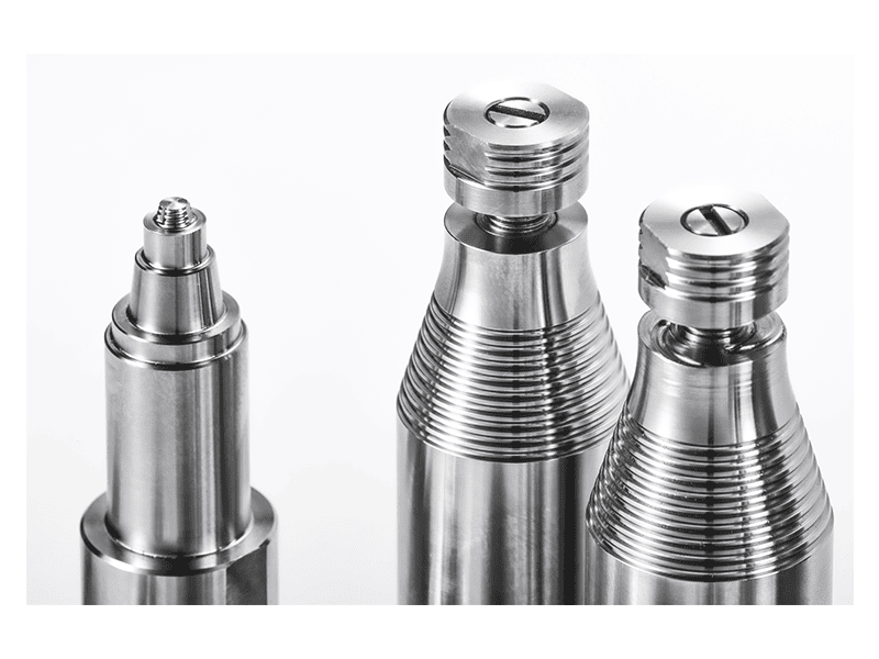
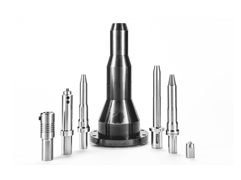
For long flat seams, a 2D gantry machine with servo-controlled welding angle keeps the tool normal to the joint; our gantry platform reaches 5000 mm/min on 6xxx at 8 mm depth. 
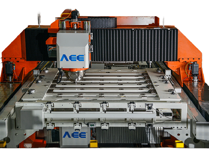
Tooling choices determine how wide the process window stays across a production batch. <AEE provides customer with optional features FSW tool> covers option decisions that affect tool adaptability on customer-specific parts.
If your tray program involves long continuous seams above 2,000 mm or closed coolant channels, it is worth confirming spindle torque and fixture rigidity before finalizing the line layout. Send your drawing to [email protected] and we will check which machine class matches the weld length and leak requirement.
How Should Battery Tray FSW Joints Be Inspected?
Leak tightness is the acceptance driver for battery trays, so inspection needs to catch both through-wall defects and latent surface defects. FSW does not produce fusion porosity, but tunnel voids, root flaws, and hooking in lap joints are real risks. A 100 percent visual check is only a first screen. For production, I recommend a combination of leak testing and internal inspection.
| Inspection method | Primary defect caught | Typical use |
|---|---|---|
| Visual | Surface flash, galling, incomplete fill | 100 percent online |
| Dye penetrant | Surface cracks and open voids | Batch sampling |
| X-ray or phased array UT | Subsurface tunnel or void | Batch or critical seams |
| Cross-section macro etch | Hooking, lack of fill, nugget size | Setup and periodic destructive test |
| Helium or pressure decay leak test | Through-wall leak paths | 100 percent for sealed trays |
| Tensile or bend | Joint strength | Batch qualification |
The retractable tool removes the exit hole, which is a common leak path when a conventional tool exits a closed seam.
What Causes Battery Tray Weld Defects and How Do You Fix Them?
Most battery tray FSW defects trace back to three sources: cold material flow, excessive shoulder pressure, or unsupported root geometry. The table below lists failures I see most often in process qualification.
| Defect | Typical cause | Correction |
|---|---|---|
| Tunnel void | Travel speed too high or insufficient force | Reduce travel speed or raise Z force |
| Flash | Excessive shoulder plunge or high rpm | Reduce plunge depth or lower spindle speed |
| Lack of fill | Pin volume too low for gap or thickness | Tighten fit-up or increase pin length |
| Hooking in lap joints | Oxide layer drawn upward from interface | Switch to butt joint or reduce penetration |
| Root flaw | Inadequate backing or root support | Add backing bar or change to bobbin tool |
| Surface galling and thinning | Rotating shoulder overheat on thin wall | Use stationary shoulder or lower heat input |
Hooking is the defect most likely to pass visual inspection but fail leak or fatigue testing. In an overlap joint, the original sheet interface can be pulled upward into the weld nugget, leaving a crack-like path. If the tray design allows it, a butt weld with a machined fit-up avoids this failure mode entirely. When lap joints are unavoidable, I keep penetration shallow and verify the interface position by macro cross-section.
How Do You Validate an FSW Battery Tray Process Before Tooling Commitment?
Payback is driven by scrap and rework, not just cycle time. Before ordering a machine, validate the process on samples cut from the same alloy and temper you will run in production. A proper feasibility study includes welding at full length, leak testing at operating pressure, and a cross-section review of at least three weld locations. Do not accept a parameter set developed on a small coupon if the production tray has a 2,000 mm seam with variable extrusion thickness.
We run this type of sample validation at Aerospace Engineering Equipment (Suzhou) before we quote turnkey lines. Send your tray drawing, weld length, and required leak rate to [email protected] or call +86 18325808715. We will confirm whether a standard gantry, double-head, or custom cell fits, and which tooling should be tested first.
What Should Buyers Ask Before Qualifying an FSW Battery Tray Line?
Is FSW suitable for all EV battery tray aluminum alloys?
Yes for 5xxx and 6xxx wrought alloys, with 6xxx used most often because it balances weldability, strength, and availability. FSW welds in 6061-T6 and 6082-T6 battery tray sections typically show lower distortion than fusion welds, although heat affected softening still reduces local strength. 7xxx alloys are more crack sensitive and require tighter parameter control. 2xxx aerospace grades are uncommon in high-volume trays. Before confirming alloy choice, run a sample weld with the same temper and surface condition you will use in production.
How much clamping force does a battery tray FSW fixture need?
A common shortcut is to calculate clamping force only from weld downforce. That underestimates thermal expansion loads on a long tray. The fixture must resist the full Z-axis forging force, prevent lateral movement, and press the seam against a continuous backing bar. For a 4 to 6 mm 6xxx tray seam, we typically design fixture reactions well above the machine’s rated Z force, with clamps positioned close to the weld line. The real requirement is rigidity: any lifting between clamps produces root flaws.
Does FSW leave an exit hole in battery tray welds?
It depends on tooling. A conventional FSW tool leaves a through hole at the end because the rotating pin retracts vertically. In a battery tray, that exit hole becomes a leak path unless it is machined away or capped. A retractable pin tool retracts the pin into the shoulder while the material is still plastic, filling the exit hole. For closed coolant channels, closed contours, or any seam where a hole cannot remain, retractable tooling is the standard choice.
What leak rate can FSW battery trays achieve?
In tray programs we have supported, the limiting factor is usually not weld strength but leak isolation between channels. A well-executed FSW seam can pass helium leak testing at automotive battery tray limits, but the result depends on root penetration, oxide control, and exit-hole strategy. Most customers specify a pressure decay or helium leak limit rather than a generic IP rating. Run the leak test on a full-length production-representative seam, not a short coupon, before freezing the process.
How do you avoid distortion on long battery tray seams?
Distortion control is really a fixturing and sequencing question, not a single parameter. Long tray seams build heat progressively, so welding from one end to the other without thermal pauses can pull the part out of flatness. We sequence welds to balance heat input, use full-length clamping, and sometimes pre-set the fixture to compensate for known springback. For high-volume lines, in-process temperature monitoring and cooling between passes are worth specifying. Share your drawing and weld sequence and we will confirm the fixture concept before you commit.
If you’re interested, check out these related articles:
AEE provides customer with optional features FSW tool
AEE attend 13th International Symposium on FSW in Kyoto, Japan on 21 – 23 May 2024
Customized Dissimilar Material Welding Manufacturers in China