
FSW Process Setup for Aluminum Extrusions vs Rolled Plates
Table of Contents
- FSW entry conditions differ between extruded and rolled aluminum
- Does the extrusion seam affect the FSW joint?
- FSW fixture and parameter setup must follow the material form
- Do extrusion walls weld faster than plate of the same alloy?
- Defect mechanisms and machine configuration split by product form
- Does the FSW machine change when switching from plate to extrusion work?
- FSW qualification exposes different risk points by form
- Choosing the right process setup for your product form
- Common questions about FSW on extruded and rolled aluminum
- Can the same FSW tool weld both extruded and rolled aluminum?
- Why does an extrusion weld show voids where a plate weld ran clean?
- Is an extrusion seam considered a weld defect?
- What machine changes are needed to switch from plate to extrusion welding?
- How do you qualify FSW for extruded versus rolled aluminum?
Friction stir welding aluminum extrusions versus rolled plate is rarely about the alloy itself. A 6061-T6 profile and a 6061-T6 sheet share chemistry, but the process sees them differently because wall thickness, grain direction, surface condition, and support stiffness all shift. In our process development work, the material form changes the FSW window more than the alloy grade does. Fixture strategy, heat input, and machine configuration come before tool design. The practical differences across surface condition, clamping force, parameter limits, and qualification checks decide whether a production weld holds.
FSW entry conditions differ between extruded and rolled aluminum
Both product forms come from the same wrought aluminum families, usually 5xxx or 6xxx, and the solid-state mechanics of FSW do not change. The tool plasticizes material below the melting point, and the nugget recrystallizes into fine equiaxed grains. What changes is what the tool first meets. Rolled plate carries a rolling texture with flattened grains in the rolling plane, and its oxide layer is dense from hot or cold rolling. The weld seam’s position relative to rolling direction changes tensile behaviour and heat-affected zone (HAZ) softening measured after welding. Extrusion carries elongated grains along the profile axis and a die-formed surface with longitudinal die lines. Hollow profiles add one or more longitudinal seam welds left by the porthole die.
Those entry conditions drive different process decisions. Plate demands attention to oxide removal or machining, especially on butt joints where a folded oxide film can remain as a kissing bond or lazy S when the shoulder cannot break and expel it. Extrusion demands attention to seam position. A porthole seam is itself a solid-state bond created inside the die, and its quality depends on extrusion temperature and pressure. When the FSW tool runs parallel and close to that seam, root flaws can nucleate along a line that is already weaker than the parent wall. We sequence the profile orientation so the FSW seam does not sit on top of the extrusion seam.
| Process factor | Aluminum extrusion | Rolled plate |
|---|---|---|
| Surface condition | Die lines, optional extrusion seam, as-extruded oxide | Rolling scale or machined surface, dense oxide |
| Grain direction | Elongated along profile axis | Flattened in rolling plane, anisotropic |
| Fixture risk | Thin wall collapse, gap opening, spring-back | Flatness variation, thermal buckling |
| Heat input window | Narrow, because walls are thin and heat sink limited | Wider, but through-thickness softening matters |
| Dominant defect | Root flaw along seam, tunnel at interface | Kissing bond, lack of penetration at root |
| Typical machine | Extra-length gantry for long profiles | Wide-bed gantry or heavy-load for thick plate |
Does the extrusion seam affect the FSW joint?
Only when it lies inside or immediately beside the weld path. A sound porthole seam is metallurgically continuous and can carry load, but it is rarely as clean as the surrounding parent material. If the FSW root reaches it, tunnel defects and root voids concentrate along the seam line. The mitigation is positional: rotate the profile so the seam sits outside the weld zone, or cut a chamfer that removes the seam from the joint root. Welding through the seam requires lower travel speed and deeper shoulder engagement, and that adds heat the thin extrusion wall often cannot accept.
Alloy mixing is the other entry-condition variable when a profile meets a plate of a different grade. <Customized Dissimilar Material Welding Manufacturers in China> covers tool selection and intermetallic control when a 6xxx extrusion joins a 5xxx plate, a pairing common in battery cooling plate and enclosure work.
FSW fixture and parameter setup must follow the material form
Clamping is where extrusion and plate diverge fastest. A rolled plate sits flat on a backing bar, and the main work is holding it against thermal expansion and tool travel force. Longitudinal and lateral clamps, a rigid backing plate, and enough preload keep the faying faces closed. Plate over about 8 mm also needs the backing bar to act as a heat sink in one direction so the weld does not soften through thickness. A hollow extrusion profile is different. The wall is thin, the section may be open or closed, and the interior may be unreachable. Clamping pressure that is fine on a 10 mm plate will deform a 2.5 mm extrusion flange, change the joint gap, and move the root position before the tool arrives.
For hollow profiles, the key choices are internal support or a self-reacting tool. If the section is open, a mandrel or shaped backing can enter the cavity. If the section is closed, a bobbin tool welds both surfaces simultaneously with no internal backing. We treat the cavity as part of the fixture, not just the part. What makes extrusion work less forgiving is that spring-back and die twist from the extrusion press remain in the profile. A profile that measured square on the table can open a 0.2 mm gap when clamping is released, and FSW will not bridge that gap the way a filler metal process would.
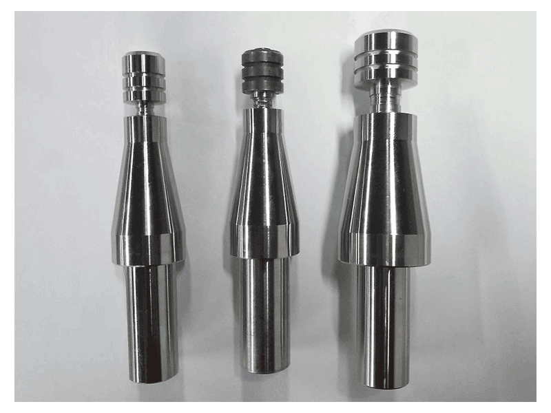
Parameter selection starts from wall thickness, not just alloy. A 2 to 3 mm extrusion wall cannot accept the same plunge depth and shoulder engagement as a 10 mm plate because it heats quickly and has little thickness margin. We typically run thin-walled 6xxx extrusions at higher travel speed and reduced rotation speed compared with plate, keeping the heat input low enough that the HAZ does not consume the full wall. The shoulder is set for light contact. A full shoulder plunge through a thin wall will thin the section and leave a root defect.
Parameter shifts between forms often turn into tooling changes, because the pin and shoulder must match the wall or plate geometry. <AEE provides customer with optional features FSW tool> covers how pin length, shoulder profile, and retraction options are specified when the same production line alternates between extrusion and plate work.
Do extrusion walls weld faster than plate of the same alloy?
Yes, within limits. Thin extrusion walls heat and cool quickly, so travel speed can be higher without overheating the nugget. The practical ceiling in production is usually set by fixture rigidity and profile straightness rather than metallurgy. Rolled plate carries a larger heat sink, so the tool stays cooler and travel speed drops to keep the plasticized volume stable. The trade-off is that the extrusion wall has almost no thickness margin, so a small plunge error produces under-thickness or root break more easily than on plate.
Defect mechanisms and machine configuration split by product form
Rolled plate welds fail at the root plane when oxide is not expelled or when penetration is incomplete. Kissing bonds and lack of penetration are the recurring issues, and both are invisible from the surface. Ultrasonic testing and phased array are standard for plate joints in aerospace and marine work for that reason. Extrusion welds fail differently. The thin wall and the internal seam make root flaws, lengthwise tunnels, and seam-linked voids the dominant defects, and they can form even when the surface bead looks continuous. A plate root flaw is usually a parameter or backing problem. An extrusion root flaw is usually a seam position or wall collapse problem.
We have seen this pattern in hollow profile development. A porthole seam only a millimetre or two from the FSW root can run clean in flat lengths and then open a tunnel exactly along the seam. Raising rotation speed does not fix it, because the problem is not material starvation but a pre-existing weak line in the wall. Moving the seam out of the root path resolves the failure without touching parameters. Plate work almost never produces that signature because there is no longitudinal seam to hide a weak path.
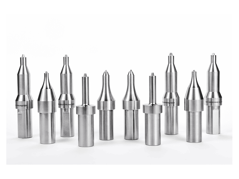
Machine configuration follows the two geometries. Extrusion work is length-first. Rail profiles, busbar housings, and battery tray side members run metres long, so the bed length and X-axis stroke define the cell. A production line for rail profiles needs an extra long gantry with a long X stroke, laser weld tracking, and often a dual-head arrangement to weld both sides in one pass. Loading and clamping must hold the unsupported spans of the profile.
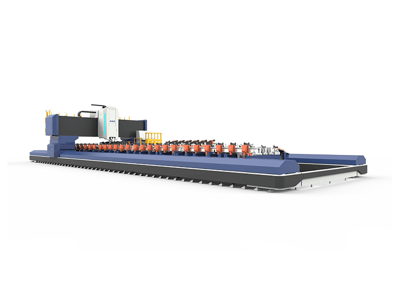
Rolled plate work is width and thickness first. Large panels for marine decks or pressure vessels require a wide-bed gantry that can reach the full plate width and keep the tool normal to the surface. When thickness climbs past 25 mm, the spindle must deliver enough torque and the frame enough stiffness to hold axial force. A heavy-load gantry sized for single-side aluminum welds up to 100 mm carries spindle torque around 872 Nm and a high-force Z-axis, which plate work routinely needs but thin extrusions almost never do.
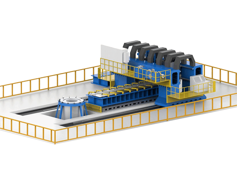
Does the FSW machine change when switching from plate to extrusion work?
The working envelope often changes, not just the program. Extrusion fixtures are long and narrow, so the machine needs X travel and profile support, but not necessarily a heavy Z-axis. Plate fixtures are wide and flat, so the machine needs Y travel and table span. Some gantry designs handle both. A cell built only for plate rarely has the length to run a 12 m rail profile, and a cell built only for thin profiles rarely has the Z force to weld 40 mm plate. Checking spindle torque, Z force, and table dimensions against both part families prevents a later retrofit.
The practical question for an engineer is not which machine is better, but which constraint dominates the part. Long thin profiles favour speed and length capacity. Wide thick plates favour force and torque. If your program involves both forms, confirm whether the spindle, clamping table, and tool changer can switch between a thin-wall extrusion fixture and a thick plate setup without rebuilding the cell. Reach out at [email protected] to confirm the machine envelope before you freeze the layout.
FSW qualification exposes different risk points by form
Qualification for extruded and rolled aluminum follows the same logic: a welding procedure specification (WPS), a procedure qualification record (WPQR), and destructive plus non-destructive testing. ISO 25239 sets the framework for aluminum FSW qualification, and most aerospace and rail customers layer additional requirements on top. The difference is where qualification fails. Plate procedure qualification usually fails on root penetration or lateral bend tests due to incomplete root fusion. Extrusion qualification typically fails on macro examination showing seam-linked voids or wall thinning beyond tolerance, sometimes with the same parameters that passed a plate coupon.
This is why the test coupon must reproduce the production form. A procedure qualified on rolled plate does not transfer to a hollow extrusion unless the essential variables are re-evaluated. The coupon should match the extrusion seam position, the internal support condition, and the actual wall thickness. If the production part is a 3 mm profile and the coupon is a 6 mm plate, the qualification result says little about production risk.
Choosing the right process setup for your product form
Most FSW trouble on extrusion and plate work starts after the weld has failed, when a seam void or a root defect has already stopped a batch. The setup decisions that would have prevented it come earlier: seam position, internal support, heat input, and machine envelope. A process engineer who pins those down against the actual product form avoids most field failures.
If your program is moving between extruded profiles and rolled plate, or you are not sure which process limits apply to your section, send the part drawings, the seam and wall thickness details, and the target production rate. We will confirm the fixture strategy, parameter window, and machine configuration against your actual product. Contact Aerospace Engineering Equipment (Suzhou) Co., Ltd. at [email protected] or +86 18325808715.
Common questions about FSW on extruded and rolled aluminum
Can the same FSW tool weld both extruded and rolled aluminum?
It depends on thickness and shoulder geometry more than on the form itself. A conventional tool with the correct pin length can weld a 6 mm extrusion wall and a 6 mm rolled plate when the clamping and backing plate match. The tool becomes form-specific when the extrusion is hollow and thin, because plunge depth and shoulder contact have less margin, or when the plate is thick enough that pin length and torque capacity change. In our practice, separate tools or a retractable pin configuration are specified when a line alternates between thin profiles and thick plate.
Why does an extrusion weld show voids where a plate weld ran clean?
The most common cause is a porthole seam or wall collapse feeding a weak line into the root, not a general parameter failure. Plate welds of the same alloy can run visually clean because rolled stock has no longitudinal seam and the backing bar holds the root closed. In an extrusion, the seam may sit close to the weld path, or internal clamping may leave a small gap the shoulder cannot close. Check seam position and internal support before adjusting rotation or travel speed.
Is an extrusion seam considered a weld defect?
Not by itself. A sound porthole seam is a solid-state bond formed during extrusion and can carry structural load. The misconception is to treat every visible seam line as a crack. The real distinction is whether the seam is bonded or unbonded. A bonded seam is an inhomogeneity, not automatically a defect. An unbonded or contaminated seam is a defect. For FSW, the concern is when the FSW root intersects a weak seam, because then the seam acts as a crack-like path for tunnel formation.
What machine changes are needed to switch from plate to extrusion welding?
In the production cells we have set up, the change is mostly fixture and travel length, not the spindle itself. A long profile needs a machine with enough X stroke and support rollers. A wide plate needs Y travel and a flat backing table. The spindle changes only when the workpiece thickness crosses a torque threshold, such as moving from 10 mm to 40 mm plate. We ask engineering teams to confirm two numbers first: the longest seam and the thickest section, then size the machine envelope to the larger of the two.
How do you qualify FSW for extruded versus rolled aluminum?
The more precise question is which essential variables change when the form changes. The qualification requirement itself does not split by form; the coupon setup does. A WPS for rolled plate transfers to extrusion only if wall thickness, seam position, backing condition, and plunge depth stay within the qualified range. Thin extrusions sit close to the edge of the heat input window, so we recommend qualifying the actual production cross-section with the real seam location and internal support. Share your drawing and the seam locations at [email protected] and we will confirm the qualification variables before testing.
If you’re interested, check out these related articles:
AEE provides customer with optional features FSW tool
Refill Friction Stir Spot Welding (RFSSW)