
FSW of Metal-Matrix Composites: Capabilities and Tool Wear
Table of Contents
- What Makes Metal-Matrix Composites Different in FSW
- What FSW Can Weld in Aluminum MMC Components
- Why Tool Wear Decides FSW Feasibility for Metal-Matrix Composites
- How to Run FSW on Metal-Matrix Composites Without Tunnel Defects
- What to Specify Before Welding Metal-Matrix Composite Prototypes
- Common Questions About FSW of Metal-Matrix Composites
- Can FSW weld MMCs with more than 25 percent ceramic reinforcement?
- Do MMC welds need a different machine than standard aluminum FSW?
- Why do MMC FSW welds sometimes show a rough surface?
- What is the most expensive mistake in MMC FSW?
Metal-matrix composites give designers high specific stiffness and wear resistance, but the ceramic reinforcement that creates those properties also abrades the welding tool. FSW of metal-matrix composites can be production capable when the process is planned around particle distribution, joint configuration, and tool material rather than machine speed alone. I treat MMC work as a tool wear problem first and a welding problem second. The capability exists, but it is not the same as welding standard 6xxx aluminum. Process limits come from heat input control, spindle force response, and how quickly the pin geometry degrades.
What Makes Metal-Matrix Composites Different in FSW
An aluminum MMC combines an aluminum alloy matrix with a hard ceramic phase, usually silicon carbide, alumina, boron carbide, or titanium diboride. The reinforcement is not consumed by the process. It stays solid while the matrix plasticizes. That changes material flow, heat transfer, and tool interaction in three ways. First, the particles resist plastic deformation and create a more abrasive environment at the pin and shoulder. Second, the particle distribution is rarely uniform through the thickness, so tool forces fluctuate along the weld. Third, the reinforcement raises the apparent viscosity of the plasticized material, which makes it harder to close the trailing cavity. A weld that looks stable on 6061 aluminum can develop subsurface voids in the same joint made from an MMC.
| Reinforcement | Weldability signal | Main tooling risk |
|---|---|---|
| SiC | High hardness, strong tool wear signal | Shoulder and pin abrasion |
| Al2O3 | Similar abrasive behavior, lower thermal conductivity | Sharp wear flats |
| B4C | Very hard, often used in aerospace | Severe tool wear, narrow window |
| TiB2 | Improved wettability and finer distribution in some alloys | Moderate wear, more stable flow |
| Hybrid blends | Mixed behavior depends on particle ratio | Uneven wear and variable weld depth |
What FSW Can Weld in Aluminum MMC Components
Where MMC parts need joining, FSW can handle butt joints, lap joints, and some T-joint configurations without melting the matrix. That is the main advantage. Fusion welding of particle-reinforced aluminum tends to produce porosity, reinforcement segregation, and solidification cracks. The solid-state nature of FSW keeps the temperature below the melting range, so those defects do not form in the same way. The joint can also be made between an MMC and a wrought aluminum alloy, which is useful for attaching an MMC brake disc or a heat sink base to a standard structure. The limitation is plastic flow. If the reinforcement fraction is too high, the matrix cannot carry enough plasticized material around the pin to form a sound nugget.
Production applications cluster where the MMC is doing a specific local job. We have seen inquiries for particle-reinforced brake rotors, power module base plates, optical benches, and wear-resistant battery tray inserts. In those cases, the MMC is not welded across the entire assembly. It is joined along a well-defined edge or perimeter. That local-weld strategy is important because it keeps the difficult material in the smallest possible weld length and leaves the rest of the component in standard aluminum.
Why Tool Wear Decides FSW Feasibility for Metal-Matrix Composites
Tool wear is not a maintenance issue in MMC welding. It is the primary feasibility criterion. The reinforcement particles contact the pin and shoulder while the matrix is softened, so the tool surface experiences continuous low-speed abrasion under welding force. A pin that loses height changes weld depth. A shoulder that loses profile changes heat input and surface consolidation. Once wear progresses, the operator compensates with more rotational speed or deeper shoulder plunge, and the new parameter set can create its own defects.
In our process trials on roughly 20 percent SiC reinforced aluminum, a PCBN tool kept its shoulder profile after several hundred millimeters, while a carbide tool showed measurable wear flats before the same distance. The difference was not just tool life. The carbide tool produced a rougher surface as the geometry degraded, and the weld depth shifted. PCBN and polycrystalline diamond tools are not optional for sustained MMC work. They are the baseline for any serious process window.
| Tool material | Wear resistance in MMC | Practical note |
|---|---|---|
| H13 tool steel | Low | Only short feasibility checks |
| Tungsten carbide | Moderate | Acceptable for low reinforcement fractions |
| PCBN | High | Standard for SiC and B4C reinforced aluminum |
| PCD | High but expensive | For fine abrasives and very long runs |
| Custom composite pin | Application specific | Pin and shoulder can use different materials |
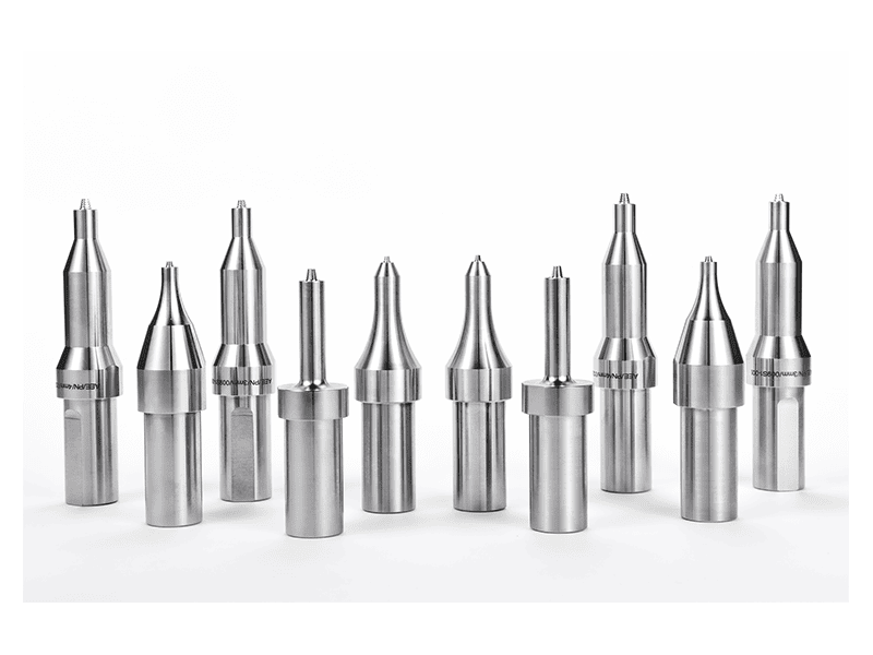
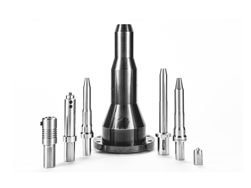
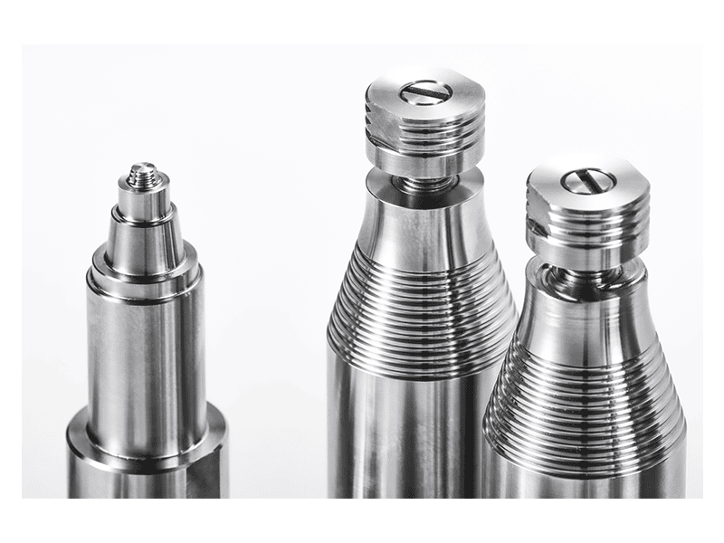
Tool wear changes weld depth, shoulder contact pressure, and surface finish at the same time. <AEE provides customer with optional features FSW tool> covers how tool features can be matched to a specific material rather than treating every MMC weld with the same standard pin.
If your MMC specification involves particle loading above 25 percent or a lap joint on a thin backing sheet, confirm tool geometry and backing pressure before you order prototypes. Send your material certificate and joint drawing to [email protected] or call +86 18325808715.
How to Run FSW on Metal-Matrix Composites Without Tunnel Defects
Tunnel defects in MMC welds are usually caused by too little plasticized matrix reaching the trailing side of the pin. The ceramic phase reduces the volume of material that can flow, so the standard remedy is not to make the weld hotter. It is to make the material flow path more deliberate. That means lower travel speed, moderate rotation, and enough axial force to keep the shoulder fully engaged.
- Start with a shorter pin than you would use for unreinforced aluminum. The reinforcement reduces flow and a shorter pin lowers the chance of an unfilled root.
- Set travel speed below the normal 6xxx aluminum value. MMC material does not consolidate at high travel speeds.
- Keep the shoulder loaded. Axial force must stay steady, because force drops produce intermittent tunnel defects.
- Use a rigid backing plate and strong clamping. The higher flow stress of MMC transmits more force into the workpiece.
- Inspect tool geometry after every development run, not after a full campaign.
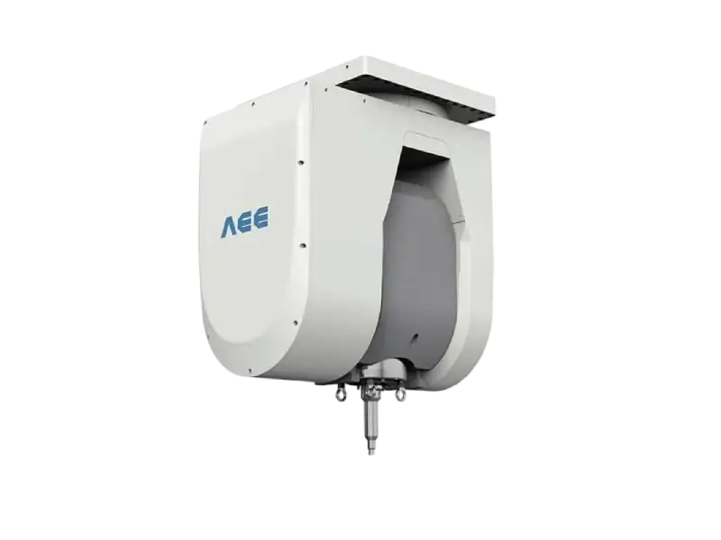
Closed contour welds on MMC parts create an exit hole problem. A retractable pin that withdraws into the shoulder at the end of the weld fills the exit region while the shoulder remains in contact. We use this approach for enclosures and annular MMC joints where a keyhole cannot be left in the finished part.
For thin MMC sections, a stationary shoulder reduces the surface heat input and leaves a smoother blend. The rotating pin still does the material work, but the sliding shoulder does not tear up the surface when the reinforcement is sharp and uneven.
What to Specify Before Welding Metal-Matrix Composite Prototypes
MMC welding programmes stall because the specification arrives as a generic aluminum drawing. The material callout may say aluminum MMC without the reinforcement type, particle size, volume fraction, or heat treatment condition. Those missing fields decide whether the weld is simple or impossible. A 10 percent TiB2 reinforced alloy with fine particles behaves differently from a 25 percent SiC material with coarse particles, even when both drawings look similar.
The specification should include five items before welding begins: matrix alloy, reinforcement type, particle volume fraction, particle size distribution, and joint configuration. We also need to know whether the weld will be inspected by X-ray, ultrasound, or sectioning, because MMC welds have a different defect signature than standard aluminum. Once those facts are fixed, the right machine class becomes clear. A small C-type machine may be enough for a 3 mm MMC power module base. A heavy-load gantry machine with 200 kN maximum Z force and 105 kW spindle power is needed for thick plates or wide panels.
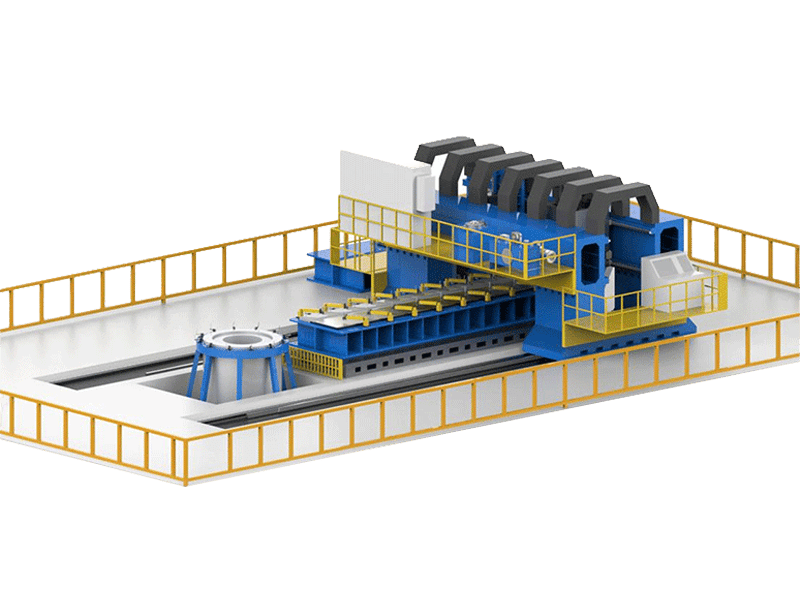
MMC work usually fails in quotation, not in welding. The buyer sends a drawing for an aluminum MMC part, the supplier quotes a standard aluminum process, and the first samples show tool wear, depth variation, or poor surface finish. That risk can be removed early. Send the material certificate, particle fraction, target weld depth, and joint drawing to [email protected] or call +86 18325808715. We will confirm the tool type, machine class, and realistic weld quality before you commit to prototype tooling.
Common Questions About FSW of Metal-Matrix Composites
Can FSW weld MMCs with more than 25 percent ceramic reinforcement?
Yes, in selected joint designs. High reinforcement fractions reduce the plasticized matrix available to flow around the pin, so the weld becomes narrower and slower. A butt joint in a plate with 25 to 30 percent SiC can be made with a PCBN tool, but a lap joint with the same material may leave root defects because the lower sheet cannot feed enough material upward. The real question is not whether the material can be welded at all, but whether the specific joint geometry gives the matrix enough room to close behind the pin.
Do MMC welds need a different machine than standard aluminum FSW?
A common assumption is that the same C-type machine will work because the part is aluminum. That underestimates the tool loads. MMCs require steady axial force, lower travel speed, and better thermal stability in the spindle than many standard aluminum welds. A machine with force control and a torque-capable spindle handles this more predictably. For thin MMC work, a C-type machine can be suitable. For thick plates, wide panels, or continuous production, a gantry or heavy-load machine with higher Z-axis capacity reduces the chance of force dips that create tunnel defects.
Why do MMC FSW welds sometimes show a rough surface?
It depends on which reinforcement dominates the tool contact. If the particles are coarse or unevenly distributed, the pin and shoulder ride over hard clusters and leave surface tearing. If the tool is already worn, a rough surface is often the first visible sign. In thin sections, a stationary shoulder can produce a much smoother finish because the shoulder does not rotate against the reinforcement. In thicker sections, surface roughness is usually a sign to stop and check tool geometry before the next weld.
What is the most expensive mistake in MMC FSW?
In our process reviews, the most frequent mistake is treating the workpiece as standard aluminum and waiting too long to inspect tool geometry. A worn pin changes depth without warning, and the next parts may pass visual inspection while failing internal quality. The cost appears later, in scrap or in a qualification test that fails after many samples. The simpler path is to define tool inspection intervals from the first MMC run. Share your material data and joint configuration with us at [email protected], and we will confirm whether the proposed weld is realistic before tooling orders begin.
If you’re interested, check out these related articles:
AEE provides customer with optional features FSW tool
Refill Friction Stir Spot Welding (RFSSW)
Customized Dissimilar Material Welding Manufacturers in China