
Aluminum Battery Housing FSW: The Shift in EV Manufacturing
Table of Contents
- What Makes Fusion Welding Risky for Aluminum Battery Housings?
- Which Design Inputs Matter Before Starting Battery Housing FSW?
- Material Condition and Alloy Selection
- Joint Geometry and Thickness Range
- Leak Tightness and Testing Requirements
- How Do Machine and Tooling Choices Affect Battery Tray Yield?
- What Does It Take to Move from Prototype to Automated Production?
- What Should You Clarify Before Ordering Battery Housing FSW Equipment?
- What Questions Do EV Manufacturers Ask About Aluminum Battery Housing FSW?
- Can FSW weld 6xxx aluminum battery housings without hot cracking?
- Is friction stir welding too slow for battery tray production?
- What wall thickness can a single FSW pass handle in a battery tray?
- Does FSW require a backing bar below the weld?
Aluminum battery housing welding has moved from a sheet metal joining step to a structural and thermal qualification problem. Battery enclosures now carry crash loads, locate cell modules, and seal coolant channels under pressure. Fusion welding struggles with that combination because high heat input creates distortion, porosity, and hot cracking in 6xxx aluminum. We work with EV suppliers on battery tray programs where leakage at cooling channel seams and distortion above 1 mm made friction stir welding the production choice. This article explains the shift, the design and equipment decisions that affect yield, and what to confirm before ordering an FSW battery housing line.
What Makes Fusion Welding Risky for Aluminum Battery Housings?
Aluminum carries a stable oxide layer, absorbs hydrogen when molten, and solidifies with a wide hot cracking range in constrained joints. A gas metal arc or laser weld on 6061 or 6082 therefore depends on shielding gas, wire feed control, and precise joint fit up. The battery housing multiplies those demands. Outer frame seams are long and restrained, floor panels span wide areas, and cooling channel webs require continuous root fusion along a narrow land. In production, these joints show porosity, incomplete fusion at lap edges, angular distortion, and leak paths that only appear after machining.
The comparison below shows where fusion welding and friction stir welding separate on the requirements that matter for a sealed enclosure.
| Requirement | Fusion welding on 6xxx battery housing | Friction stir welding |
| Porosity risk from hydrogen and oxide | High, especially in lap joints | Low because the material stays below melting point |
| Hot cracking sensitivity in constrained seams | High in 6xxx alloys | Minimal |
| Distortion after welding | Significant from high heat input | Lower, especially with stationary shoulder tooling |
| Coolant channel leak path control | Sensitive to wire feed, gap, and shielding | Continuous solid-state root penetration |
| Heat affected zone softening | Pronounced in age hardened alloys | Reduced, though still present at the weld boundary |
Friction stir welding removes most of these failure mechanisms. The rotating tool heats the joint by plastic deformation, so the aluminum reaches a softened state below the melting point. Porosity from solidification disappears, hot cracking cannot form, and no filler metal or shielding gas is required. The same weld also leaves the heat affected zone narrower, which matters when the housing is load bearing and the design already trims wall thickness for mass.
Many battery housing seams are closed contour. <AEE provides customer with optional features FSW tool> covers how optional functions such as force control, position control, torque monitoring, and laser tracking change the process window for those seams.
Which Design Inputs Matter Before Starting Battery Housing FSW?
Qualification starts with the part print, not with the machine. The material condition, joint section, and test boundary decide whether the seam is feasible in one pass or whether it requires a backing bar, a different shoulder, or a second operation.
Material Condition and Alloy Selection
Aluminum extrusions in battery tray frames are commonly 6061-T6 or 6082-T6. Floor sheets and cooling plates may use 3003, 6060, or another work hardened grade. FSW handles all of these, but the pin and shoulder must match the flow stress of the alloy. Heat treated extrusions accept the short thermal cycle well, while work hardened sheet can soften more readily. If the design adds steel brackets or copper busbars near the aluminum channels, the joint is no longer a single-material problem.
When a housing adds steel brackets or copper busbars near aluminum channels, <Customized Dissimilar Material Welding Manufacturers in China> covers how intermetallic control and tool selection change the qualification path.
Joint Geometry and Thickness Range
Most battery housing seams fall between 2 mm and 8 mm in 6xxx aluminum. In that range, a conventional or stationary shoulder tool can weld butt, lap, and fillet details with proper clamping. Above 8 mm or on hollow sections, a bobbin tool or a heavy-load spindle becomes more practical. A long straight extrusion seam is easier to automate than a curved cover channel. A closed loop with no exit allowance creates a keyhole problem unless the machine uses a retractable pin tool.
Leak Tightness and Testing Requirements
Cooling plate circuits are normally checked by helium or pressure decay after welding. The weld must show continuous root fusion and no tunnel defect. FSW meets that requirement when clamping force keeps the parts closed during tool travel. The inspection point should be set after welding and before machining, because later drilling or tapping can create leak paths that are wrongly assigned to the weld.
If your battery tray mixes long frame extrusions with narrow cooling channel webs, do not assume one tooling package covers both. Send your part cross sections and annual volume to [email protected] and we will confirm whether a gantry or dual-worktable configuration keeps both seams inside one process window.
How Do Machine and Tooling Choices Affect Battery Tray Yield?
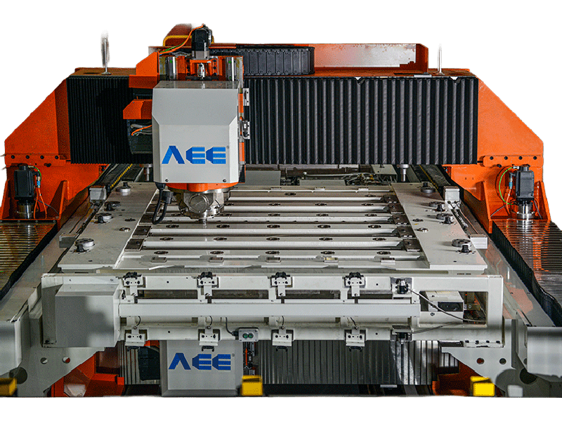
Yield is set by how the machine applies force, not by spindle power alone. A battery tray line needs a spindle with enough torque at the tool speed, a fixture that holds the long frame without lifting, and a control system that responds to local thinning or gap movement. For long outer frame seams, a gantry layout works because the machine can carry the fixture and hold the seam straight over several meters. For smaller sealed parts inside the pack, a dual-worktable C-type machine keeps one part loading while the other welds, which cuts cycle time without forcing the process faster than the tool can handle.
On 6xxx battery grades, our gantry FSW machines are rated for 8 mm welding depth and up to 5000 mm per minute travel. The usable speed on a given part still depends on the joint width and the tool shoulder size.

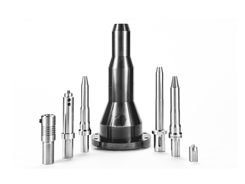
Tool selection affects yield just as much. A retractable pin tool closes the exit hole in a one piece housing without a separate plug or keyhole drill. A stationary shoulder tool lowers surface roughness and heat input, which matters when a thin wall or a cosmetic cover surface sits above the channel. Bobbin tools remove the need for a backing bar on hollow sections, but they demand more from clamping and part straightness.
What Does It Take to Move from Prototype to Automated Production?
A feasibility weld on a cut blank does not predict a production line. The first step is tool and parameter development on the full part section, with force and position data recorded. Then the clamping concept is proven, because a battery tray can lift under thermal expansion long before the tool reaches mid seam. After that, the line layout adds handling, part detection, seam tracking, and weld data traceability. In battery tray production, a double-head machine can weld both sides of an 8 mm joint in one handling operation, which removes the need to turn the part between passes.
At scale, the value of the FSW line is not the single weld. It is the ability to run the same force envelope, spindle speed, and travel rate on every part while the control records a traceable torque and temperature history. That record is what lets the line produce to a welding procedure specification instead of depending on operator judgment.
Process research keeps shifting the boundary of what production lines can qualify. <AEE attend 13th International Symposium on FSW in Kyoto, Japan on 21 – 23 May 2024> covers the research directions and production priorities discussed at that event.
What Should You Clarify Before Ordering Battery Housing FSW Equipment?
An EV pack carries high warranty risk after the welding process is frozen. A leak found during pack assembly costs more than a weld defect caught at the line, and a distorted frame discovered in pack fit-up can stop an entire station. The most useful step before ordering equipment is to benchmark the actual part section on an FSW machine and measure distortion, root quality, and cycle time with the same tooling and clamping concept. Then spec the line with force control, laser seam tracking, and the correct pin tool for closed contours. Send your part drawing, material grade, and monthly volume to [email protected] or call +86 18325808715. We will return a welding feasibility note and a machine configuration that fits the part, not a generic battery tray line.
What Questions Do EV Manufacturers Ask About Aluminum Battery Housing FSW?
Can FSW weld 6xxx aluminum battery housings without hot cracking?
FSW does not produce hot cracking in 6xxx alloys because the material never reaches a fully molten state. The tool heats the joint through plastic deformation, so the solidification mechanisms that cause fusion weld cracks are not present. The benefit is not automatic. A pin shape that is wrong for the alloy can still create tunnel defects or surface tearing. That is why each extrusion lot is released with a section cut and bend test before production welding.
Is friction stir welding too slow for battery tray production?
Not if the line is configured around the seam length, not around a single weld speed. A short stitch weld can be slow in arc terms and still finish the part faster because there is no preheat, wire feed, shielding gas, or grind. For long outer frame seams, a gantry FSW machine runs continuous travel while the fixture holds both profiles. Effective throughput then depends on loading, clamping, and tool change more than on the welding speed alone.
What wall thickness can a single FSW pass handle in a battery tray?
It depends on the alloy and whether the joint is a solid section or a hollow profile. In 6xxx aluminum, a conventional tool can handle 2 mm to 8 mm in one pass when the backing is rigid and the pin length matches the part. Above 8 mm or on hollow sections, a bobbin tool or double-sided setup becomes more practical because the root side must also be forged. The decision should come from a macro section, not from a capacity chart alone.
Does FSW require a backing bar below the weld?
In production battery tray programs, we use both configurations. A rigid backing bar produces the cleanest root on a solid floor panel and keeps the sheet from lifting under axial force. For long hollow sections where a backing bar cannot reach the root, a bobbin tool applies a second shoulder from the bottom and removes the problem. The right choice follows joint accessibility and the required leak rate. If you are still deciding the seam type, share the cross section and production target with us at [email protected] and we will confirm which tooling route fits before you commit.
If you’re interested, check out these related articles:
Refill Friction Stir Spot Welding (RFSSW)
AEE provides customer with optional features FSW tool
AEE attend 13th International Symposium on FSW in Kyoto, Japan on 21 – 23 May 2024