
Ultrasonic Phased Array Testing for FSW Welds: What UT Finds
Table of Contents
- A Different Ultrasonic Strategy for Friction Stir Welds
- Flaw Types Ultrasonic Testing and Phased Array Can Detect
- Conventional UT Catches Volumetric Voids First
- Phased Array Adds Sector Scanning and Sizing
- Root Flaws and Kissing Bonds That Demand a Stricter Scan Plan
- Inspection Planning Around FSW Process Realities
- When Process Data Changes the UT Interpretation
- Process Decisions Triggered by Ultrasonic Results
- Common Questions About Ultrasonic Testing of FSW Welds
- Can ultrasonic testing find all FSW defects?
- Is phased array always better than conventional UT for FSW?
- Does a clean ultrasonic scan guarantee a strong FSW joint?
- What frequency should be used for thin and thick FSW welds?
Ultrasonic phased array testing for FSW welds detects the internal flaws that drive most joint failures: root-side lack of penetration, buried voids, tunnel defects, and kissing bonds. The harder problem is what a conventional scan can miss, because friction stir welds do not fail like fusion welds and should not be inspected with a generic fusion-weld scan plan. The right approach treats ultrasonic testing as a process diagnostic, not merely a pass/fail gate, and matches the probe angle, frequency, and scan direction to the specific flaw mode.
A Different Ultrasonic Strategy for Friction Stir Welds
Fusion welding creates a molten pool, and most ultrasonic acceptance criteria grew up around that assumption. FSW is solid state, so the defect population is different. The largest threats in an aluminium FSW joint are not gas porosity or hot cracks; they are incomplete material mixing, joint line remnants, root-side lack of penetration, hooking in lap welds, and tight kissing bonds. These flaws often sit at shallow angles, follow the original faying surface, or hide at the root where a zero-degree longitudinal scan from the crown side returns weak signals.
That changes the inspection logic. A scan plan copied from a fusion weld procedure usually looks straight down from the weld face, but that beam is nearly parallel to many FSW defect planes. The flaw may be present and still produce no clear echo. For this reason, qualified FSW inspection plans specify angle beams, sector scanning, or a combination of pulse-echo and transmitted signal paths, not just a single zero-degree check.
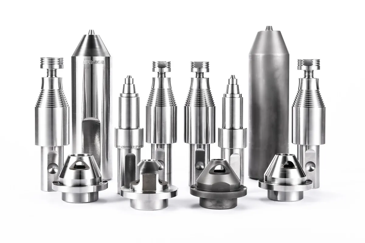
Tool geometry also fixes where defects are likely to form. A worn pin or the wrong shoulder profile will move the weak zone from the crown to the root or from the advancing side to the retreating side. The ultrasonic scan plan should be built around the actual tool path and joint configuration rather than a standard weld class alone.
Flaw Types Ultrasonic Testing and Phased Array Can Detect
Conventional UT and phased array are not two versions of the same result. They answer different questions.
| Defect type | Conventional UT challenge | Phased array contribution |
|---|---|---|
| Tunnel or wormhole void | Detectable when above about 1 mm, but sizing depends on orientation | Sector scan maps depth, length, and position along the weld |
| Root lack of penetration | Often hidden by beam spread and the root geometry | Angled beams steer into the root corner and improve detection |
| Kissing bond | Minimal acoustic opening, so no strong reflector | High-frequency focused probes can indicate a weak bond, but not always |
| Lap joint hooking | Tight oxide interface overlaps the plate interface | Multiple angles separate the hook tip from the joint line |
| Oxide entrainment or lazy S | Poor signal-to-noise when the defect is thin and oriented | Beam steering plus process-log correlation improves confidence |
Conventional UT Catches Volumetric Voids First
A conventional 4 MHz or 5 MHz compression probe finds tunnel voids and wormholes reliably when they have enough volume. A transverse scan across the weld with a focused beam gives a better length estimate than a longitudinal scan. The limitation is sizing and boundary resolution: a small void near the root may be reported as part of the backwall signal, and a tight plane may not reflect at all.
Phased Array Adds Sector Scanning and Sizing
Phased array changes the value of the scan because one probe can sweep a range of angles across the weld in a single pass. That makes shallow defects and root flaws easier to separate from clutter. It also gives a cross-sectional image that connects the indication depth to a known FSW zone, such as the weld nugget boundary or the root face. In production, this is less about finding more defects than about deciding whether an indication is real.
Root Flaws and Kissing Bonds That Demand a Stricter Scan Plan
Root lack of penetration is the defect most likely to survive an undemanding scan. It occurs when the pin does not fully mix the original faying surfaces at the weld root, leaving a thin unconnected line that opens only under load. Since the defect plane is often perpendicular to the plate surface and sits at the back wall, a crown-side longitudinal beam can be parallel to it and return no clear echo.
Kissing bonds are harder. There is often no volumetric gap, only an oxide-decorated interface with poor metallurgical bonding. The acoustic impedance difference is small, so the signal may be weak enough to be rejected as noise. A phased array scan with a high-frequency probe and a tight focal law can sometimes indicate these bonds, but it should be paired with a process parameter review. A clean signal is not sufficient proof of bond quality.
For dissimilar joints, the beam path changes because the base materials have different sound velocities and attenuation. A scan plan qualified on 6061 aluminium will not transfer directly to aluminium-copper or aluminium-steel joints.
When a phased array scan is set for an aluminium weld, a dissimilar joint changes the beam path and noise floor before any defect is separated. <Customized Dissimilar Material Welding Manufacturers in China> covers why dissimilar material FSW programs re-validate tooling, fixturing, and process windows, and why the inspection plan cannot be carried over from same-alloy production without adjustment.
Inspection Planning Around FSW Process Realities
An inspection plan should start from the process, not from a generic weld acceptance table. The tool shoulder diameter, pin length, pin shape, plunge depth, and tool wear condition all change where a defect forms and what its orientation will be. A scan plan that passes a test coupon may lose sensitivity at the end of a long production run when the pin is worn and the root condition changes.
If your application carries a leak-tight or fatigue requirement, it is worth confirming the scan plan against the actual root geometry before finalizing your acceptance class. Send the joint drawing, material grade, and production process description to [email protected] and we will confirm which ultrasonic technique fits.
The process monitoring data should be read alongside the ultrasonic result. On our FSW machines, force, torque, and temperature are logged against the weld position. When a phased array scan shows a root indication, the machine log usually shows a matching force or temperature excursion. That correlation turns the inspection result from a binary call into a diagnostic input.
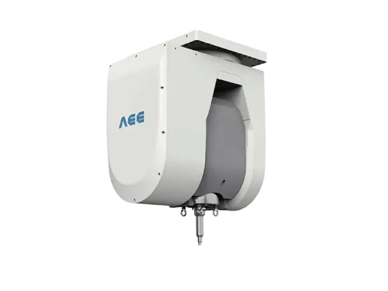
Paired inspection is stronger when the tool and machine data are traceable. <AEE provides customer with optional features FSW tool> covers how optional process monitoring, laser tracking, and tool inspection features build a traceability record that separates process variation from a real weld defect.
When Process Data Changes the UT Interpretation
A temperature drop at the root often correlates with a short plunge or a worn pin, and the same location will be where the sector scan shows a root indication. Without the process data, a small signal might be called noise. With it, the signal becomes a condition to investigate. We have found that pairing a phased array sector scan with force and torque logs resolves many ambiguous indications before destructive sectioning is needed.
Where the program uses ISO 25239 for aluminium FSW, the acceptance class determines which discontinuity sizes are relevant. The scan plan then has to be able to resolve that size, not just find any indication.
Process Decisions Triggered by Ultrasonic Results
An ultrasonic result is only useful if the plant knows what to change. A report that says “root indication, reject” does not tell the engineer whether to adjust tool length, plunge depth, travel speed, or spindle tilt. That ambiguity is the main reason FSW inspection programs stall.

AEE engineering reviews ultrasonic indications together with process logs and tool condition. We work through the likely source of the signal before creating a revised scan plan or welding procedure. Send the weld drawing, alloy grade, acceptance class, and the UT result to [email protected] or call +86 18325808715. We will confirm which process variables to address and the next test sequence.
Common Questions About Ultrasonic Testing of FSW Welds
Can ultrasonic testing find all FSW defects?
No. Ultrasonic testing finds volumetric flaws and the larger planar flaws when the beam angle and probe frequency are matched to their orientation, but it cannot detect a metallurgically weak bond that has no acoustic opening. Root lack of penetration can be detected when the scan plan is set up for it, but a zero-degree crown scan alone will miss many root flaws. Use ultrasonic testing as one part of a broader inspection package that includes process monitoring and selective destructive testing.
Is phased array always better than conventional UT for FSW?
Phased array is often treated as the automatic upgrade, but it is not automatically better. If the operator uses a narrow sector and a low-frequency probe, phased array can miss the same tight root flaws as conventional UT. Its real advantage comes from sector scanning, multiple angles, and image-based sizing. When the weld is thin and the root geometry is simple, a well-qualified conventional UT scan with two angle beams may work just as well.
Does a clean ultrasonic scan guarantee a strong FSW joint?
It depends on the loading mode and the defect type. A clean scan is strong evidence against large volumetric flaws, but it does not prove that a kissing bond is absent or that the local hardness meets the design requirement. In fatigue-sensitive or leak-tight applications, a clean UT signal needs process data and periodic macrographic sections before full production release.
What frequency should be used for thin and thick FSW welds?
In the process development work we have carried out, frequency follows thickness more than defect type. For aluminium welds up to roughly 8 mm, a 7.5 MHz or 10 MHz phased array probe gives the resolution needed for root flaws and hooking. Thicker sections above 25 mm need a lower frequency, commonly 2.25 MHz to 4 MHz, to achieve penetration. The exact choice also depends on surface condition, plate curvature, and the acceptance class. Share your material grade, thickness, and acceptance criteria with [email protected] and we will confirm the frequency and scan plan.
If you’re interested, check out these related articles:
AEE provides customer with optional features FSW tool
Refill Friction Stir Spot Welding (RFSSW)