
3D FSW Machines for Curved and Complex-Surface Welding
Table of Contents
- What Changes When the Seam Leaves the Plane
- Machine Kinematics, Stiffness and Force Control
- Components That Justify Three-Dimensional Path Control
- Fixtures and Backing Support on a Curved Seam
- Tool and Spindle Choices for Curved and Closed Contours
- Closing a seam without leaving a keyhole
- Thin walls and heat input
- Writing a Specification You Can Hold a Supplier To
- Where a Three-Dimensional Machine Is the Wrong Purchase
- Send the Seam, the Alloy and the Acceptance Standard
- FAQ
- Can a 3D FSW machine weld flat parts as well?
- What thickness can a three-dimensional platform handle?
- Does the machine eliminate the exit hole?
- How do I check that the tilt range is sufficient?
- References
A 3D FSW machine earns its cost only when the weld seam leaves the plane. As long as every seam sits on a flat plate or a flat circular path, a two-axis machine with a rotary table does the work, and a tilting head adds cost without adding capability. Once the seam follows a curved surface, such as a domed end, a non-planar housing flange or a profiled panel, the tool axis has to stay normal to the material at every point, and the axial force has to stay aligned with that moving axis. The purchase decision is therefore a kinematic and stiffness decision before it is a welding decision, and the weld result still depends on the fixture and on a procedure qualified for the part.
What Changes When the Seam Leaves the Plane
Three-dimensional friction stir welding is not a label for a machine with extra axes. It describes a seam whose path does not lie in one plane, so the tool axis must rotate to stay normal to the workpiece while it travels. ISO 25239-1:2020 sets the vocabulary for aluminium friction stir welding, and the distinction that matters to a buyer is not the axis count in the brochure but what the seam demands [1].
On a flat seam the shoulder presses evenly and the small forward tilt that pushes material behind the tool stays constant. Tilt the workpiece surface without tilting the tool and the contact changes. One edge of the shoulder digs in, the opposite edge lifts, and the forging pressure that consolidates the nugget stops being symmetric. Plunge depth drifts as well, because a vertical Z axis measures height against a surface that is no longer level. The seam can look closed on the crown and still carry a root defect, or show periodic wormhole where the shoulder lost contact.
Four seam classes cover most production parts, and only the last one needs a three-dimensional head.
| Seam class | Tool axis during the pass | Axes required | What fails when it is forced onto a simpler machine |
|---|---|---|---|
| Straight seam on flat plate | Vertical, fixed | X or Y plus Z | Nothing, this is the design case |
| Contour seam on flat plate | Vertical, fixed | X, Y, Z | Dwell marks at corners, path error on tight radii |
| Circular seam on a flat part | Vertical, part rotates | X, Y, Z plus C table | Nothing while the seam stays in one plane |
| Seam on a curved surface | Tilts with the local surface normal | X, Y, Z plus A and C | Uneven shoulder contact, drifting plunge depth, one-sided flash |
A rotary table is often sold as three-dimensional capability. It is not. A wheel rim, a filter housing or a motor end cap welded on a rotating table is a planar circular seam, and the tool never changes its angle relative to the part. That job runs on a two-dimensional platform, usually faster and at lower cost. The fourth row is where the A and C axes start to matter, and where the fixture and the backing have to follow the contour as well.
Machine Kinematics, Stiffness and Force Control
The kinematic requirement is easy to state. Two rotary axes on the welding head, one to tilt the spindle and one to rotate it about the vertical, plus enough linear travel to reach every point on the seam. The difficulty is stiffness. When the head swings, the tool centre point moves off the load path, and the reaction at the tool, which is the forward resistance plus the upset force under the shoulder, now acts on a lever arm. A head that is rigid in the vertical position can deflect at full tilt.
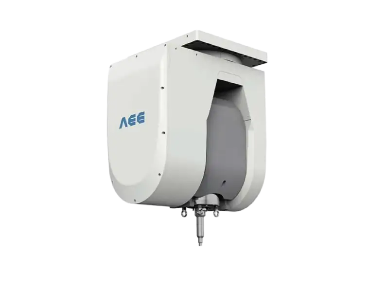
The two three-dimensional models in the AEE range show how the class splits. Both use a high-rigidity AC swing head, with the A axis covering plus or minus 100 degrees and the C axis continuous, so the tool can be presented to a surface from either side of vertical.
| Parameter | 3D platform 12×40/3 | 3D platform 20×80/3 |
|---|---|---|
| Working table and travel X, Y, Z | 3000 × 4000 mm; 4000, 3000, 1500 mm | 4200 × 8000 mm; 8000, 4500, 1500 mm |
| A and C axes | ±100° and ±360°, 2 rpm | ±100° and ±360°, 2 rpm |
| Maximum welding thickness | 12 mm | 20 mm |
| Spindle | 3000 rpm, 200 Nm, 20.9 kW | 1500 rpm, 300 Nm, 28 kW |
| Maximum axial force | 40 kN | 60 kN |
| Positioning accuracy and repeatability | 0.05 mm and 0.03 mm | 0.05 mm and 0.03 mm |
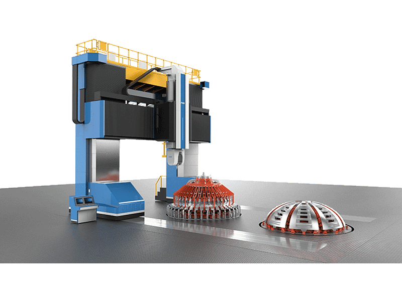
The rotation speed of the rotary axes matters more than the positioning figure on short, tightly curved seams. At 2 rpm a 100 degree tilt takes several seconds, and a seam that reverses direction repeatedly spends much of its cycle waiting for the head. Where cycle time matters, ask for angular speed and acceleration of A and C, not only their resolution.
Force control is the second half of the problem. On a formed or machined curved part, the real surface sits away from the nominal surface, and the deviation changes along the seam. Under pure position control, that deviation becomes a plunge-depth deviation, which is one of the direct causes of root defects. Force control holds axial force and lets Z follow the surface, but it stays stable only when the structure is stiff and the sensor is fast enough for the travel speed. Most production machines combine the two, with force control in Z inside position limits, so a missing part or a fixture fault cannot drive the head into the table.
A datasheet describes an envelope, not a weld. The table states that the larger platform can reach a 20 mm section at 60 kN. It does not state that a given alloy and temper at that thickness will pass a bend test, and that question is answered by a procedure qualification on your geometry, not by a brochure.
Components That Justify Three-Dimensional Path Control
Decide from the seam, not from the part drawing alone. Sample the surface normal along the seam curve and record the total angular variation the head has to cover. If the variation fits inside the fixed tilt the process already applies, a two-dimensional machine welds the part once the fixture orients it correctly. If the variation is larger, the head has to move, and the next questions are how much tilt and how much reach.
Planar circles cover more parts than buyers expect: wheel rims, filter housings, motor end caps, flange rings. Domed vessel ends, non-planar housing flanges, profiled heat sinks and curved structural panels sit in the other group, because the normal rotates through the pass. Automotive, communication and electronics work accounts for most current demand for this machine class, usually on housings and cooling components whose seam follows a machined contour.
Curved seams also appear in dissimilar joints, such as aluminium to copper in power-electronics cooling paths. There the kinematic envelope rarely limits the joint. Tool material, interface temperature and intermetallic growth control do.
Curved joints between dissimilar metals add a second constraint, because tool material and intermetallic growth at the interface affect joint strength more than the kinematic envelope does. <Customized Dissimilar Material Welding Manufacturers in China> covers custom dissimilar material welding work for buyers comparing suppliers.
Fixtures and Backing Support on a Curved Seam
Backing is where curved seams fail in practice. A flat anvil behind a curved seam leaves a gap that changes along the path, so the material has somewhere to go instead of being forged against a solid surface. The visible crown can look acceptable while the root lacks penetration.
Three approaches work. A conformal backing machined to the part contour keeps contact along the whole seam and is the most direct answer, at the cost of a fixture per part family. A self-reacting bobbin tool removes the backing question entirely, because the second shoulder reacts against the lower surface; the trade-off is that the seam must be accessible from both sides and the thickness must suit the tool. A sacrificial backing strip can be used where neither is practical, provided the strip material and its removal are accounted for in the process.
Bobbin tools are usually specified for 3.0 to 20.0 mm of aluminium, covering the 4XXX, 5XXX and 6XXX families as well as higher-strength alloys. Welding both surfaces at once removes the lack-of-penetration route. The same geometry that makes them attractive for hollow profiles makes them unsuitable for a closed box that cannot be opened for the lower shoulder.
Clamping deserves the same attention. The fixture has to carry the axial force of the head, which is 40 kN on the smaller platform and 60 kN on the larger one, and a curved part offers fewer flat surfaces for clamps than a plate does. Clamp positions that work on a flat seam can pull a curved part out of shape before the weld starts, and the seam then drifts away from the tool.
Tool and Spindle Choices for Curved and Closed Contours
Closing a seam without leaving a keyhole
A closed contour ends where it started, and a conventional pin tool leaves the hole it made on entry. Three ways out: run onto a sacrificial tab that is cut off afterwards, accept the hole outside the functional area, or use a retractable tool that withdraws the pin into the shoulder and lets plasticised material fill the cavity. The third option keeps the seam inside the part and removes a machining step.
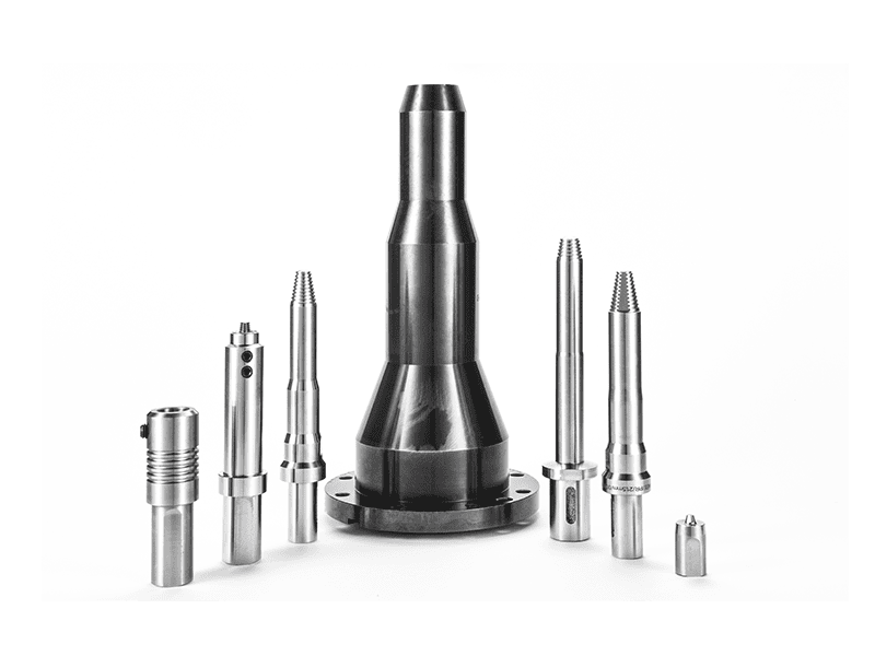
Where a closed contour returns to its starting point, the exit strategy decides whether a machining step stays in the route. <Refill Friction Stir Spot Welding (RFSSW)> covers how a refill cycle backfills the spot to leave a flat surface without an exit hole.
Thin walls and heat input
Wall thickness below about 2 mm shifts the constraint from force to heat. A rotating shoulder drags material and thins the section under it. A stationary shoulder separates the two functions, with the pin rotating while the shoulder slides on the surface. That lowers heat input, removes flash and stops the thinning that otherwise shows up as a step along the seam. The same tool suits fillet welds and materials that conduct heat poorly, where a rotating shoulder would overheat the surface.
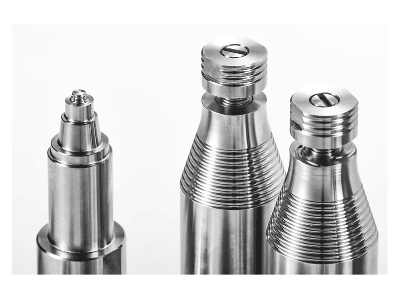
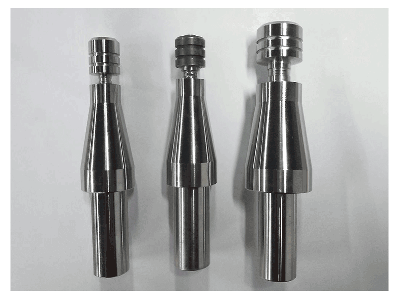
Spindle choice follows from torque at welding speed, not from the maximum speed on the label. A 12 mm aluminium seam and a 20 mm seam demand different torque, and the platform offering 3000 rpm usually offers less torque than the one offering 1500 rpm. When the head tilts, the spindle bearings also see a combination of axial and radial load that the vertical case does not produce, which is one reason a swing head is built around a large bearing and a rigid housing rather than a standard milling head.
Tool holders follow the torque class: BT40 for the lighter spindles, BT50 for the heavier ones, matched to the pin tool so that runout stays inside process tolerance. Runout matters more on a curved seam, because the tool is presented at an angle and any eccentricity becomes a varying shoulder gap around the circumference.
Writing a Specification You Can Hold a Supplier To
A short RFQ produces a short answer, and the answer is usually a machine class rather than a machine. The fields below change what a supplier quotes and what the machine must deliver.
| RFQ field | What to request | Why it matters |
|---|---|---|
| Seam definition | CAD or scan of the seam curve with surface-normal range and minimum radius | A tilt range that looks adequate on nominal CAD can run out of travel on a formed part |
| Alloy, temper and thickness range | Every combination across the seam, not the nominal thickness | Force and torque demand rise with alloy strength, and heat-treatable alloys soften in the heat-affected zone |
| Force and torque at the worst section | Axial force and spindle torque at the thickest or widest section | A platform rated for 20 mm in one alloy can sit at its limit in another |
| Keyhole strategy | Retractable tool, run-out tab, or an accepted exit hole outside the functional area | Decides whether a machining step and its cost stay in the route |
| Fixture and backing ownership | Who designs, who proves, and what evidence is supplied | Root defects on curved seams usually trace to fixture geometry, not parameter settings |
| Acceptance basis | Standard, NDT methods, sample quantity and who witnesses | A demonstration weld proves a demonstration, not a production release |
A typical opening line such as “3D FSW machine, 20 mm aluminium, please quote” can be replaced with something a supplier can price: alloy and temper, thickness range across the seam, the seam curve with its surface-normal variation and minimum radius, axial force and torque at the thickest section, keyhole requirement, who owns fixture and backing design, acceptance standard and NDT methods, annual volume and takt time.
Acceptance is where many projects separate. ISO 25239-3:2020 sets out how a welding procedure is qualified for aluminium friction stir welding, which means a qualification record tied to a specific alloy, thickness and joint configuration rather than to the machine [2]. ISO 25239-5:2020 covers quality and inspection requirements [3]. A demonstration weld on a flat coupon does not qualify a curved seam, and a machine acceptance test does not replace a procedure qualification.
Where a Three-Dimensional Machine Is the Wrong Purchase
Four conditions argue against buying one. If every seam is planar, a two-dimensional platform with a rotary table is cheaper, stiffer and quicker to service. If the seam has tight concave radii or sits inside a deep pocket, the swing head may not physically reach it, because the head body is larger than the tool. If the section is thin, below about 1 mm, the outcome is settled by backing, clamping and heat input rather than by the kinematic envelope, and a stationary shoulder tool on a simpler platform may do the work. If the section is thick, above roughly 20 mm in aluminium, the platform class changes to a heavy-load gantry machine with a much larger force capacity, which runs one-dimensional or two-dimensional paths, and buying three-dimensional motion at that force level is expensive.
Robot-based friction stir welding is the other comparison. A robot offers reach and flexibility at lower stiffness, which suits thin sections and low force, and it is a poor match where the process needs 40 kN or more. The cost of the extra axes is not confined to the purchase price. A five-axis head needs kinematic calibration and periodic re-checking, and its accuracy depends on the fixture repeating the part position, so the fixture budget rises with the machine budget.
Send the Seam, the Alloy and the Acceptance Standard
A feasibility assessment answers a narrower question than a quotation: whether the seam can be reached, whether the backing is practical, and whether force and torque fit the platform. Send the part drawing or CAD model with the seam curve marked, alloy and temper, thickness range, the surface-normal variation along the seam, the keyhole requirement, your fixture concept, the acceptance standard and NDT methods, annual volume and takt time. Aerospace Engineering Equipment (Suzhou) Co., Ltd. reviews these against the platform envelope before quoting. Email [email protected] or call +86 18325808715.
FAQ
Can a 3D FSW machine weld flat parts as well?
Yes, and many owners run both. The limitation is economic rather than technical. A tilting head costs more, and its stiffness at full tilt is lower than a dedicated vertical head on the same frame size. If most of your seams are planar, a two-dimensional machine plus an outsourced route for the curved parts is often the better first purchase, and it leaves the process knowledge in house for the day the curved work becomes routine.
What thickness can a three-dimensional platform handle?
The two common classes cover 12 mm and 20 mm of aluminium at 40 kN and 60 kN of axial force. Thickness alone is a weak specification, because force demand rises with alloy strength and weld width as well as depth. A 20 mm section in a soft alloy and a 20 mm section in a high-strength alloy are different duty for the same machine, and the second may need the larger class or a heavier frame.
Does the machine eliminate the exit hole?
No. The hole is closed by the tool and the machine’s retraction control acting together. A retractable tool withdraws the pin into the shoulder while the head holds position, so plasticised material fills the cavity. The same tool on a machine without retraction control cannot finish the seam, so ask for the combination rather than either item separately.
How do I check that the tilt range is sufficient?
Sample the surface normals along the seam, ideally from a scanned part rather than nominal CAD, and compare the total angular variation with the A axis range plus the fixed tilt. Remember that the head body, not just the tool, needs clearance, so the limiting point is usually the deepest concave region of the part rather than the steepest wall.
References
[1] ISO 25239-1:2020, “Friction stir welding — Aluminium — Part 1: Vocabulary,” ISO, 2020.
[2] ISO 25239-3:2020, “Friction stir welding — Aluminium — Part 3: Qualification of welding procedures,” ISO, 2020.
[3] ISO 25239-5:2020, “Friction stir welding — Aluminium — Part 5: Quality and inspection requirements,” ISO, 2020.
If you’re interested, check out these related articles:
Refill Friction Stir Spot Welding (RFSSW)
Customized Dissimilar Material Welding Manufacturers in China