
Heavy-Load FSW Machines for 100 mm Aluminum and 35 mm Copper
Table of Contents
- Why Thick Sections Strain the Machine More Than the Tool
- What a Heavy-Load FSW Machine Must Deliver at 50 to 100 mm
- How Welding Copper Plate Differs from Aluminum
- Which Tool Geometry Works at 100 mm
- Spindle Torque and Cooling at Low Rotation Speed
- Fixtures, Backing Support and Heat Flow in Thick Plate
- Two Ways to Weld Both Sides
- How to Specify and Qualify a Heavy-Load Machine
- Fields to Put in the RFQ
- What a Trial Weld Proves and What It Does Not
- Site and Utility Requirements
- Send the Thickness and Alloy Before You Compare Machines
- FAQ
- What is the maximum thickness a heavy-load FSW machine can weld?
- Can copper plate be welded thicker than 35 mm?
- Is a 200 kN machine always required for 60 mm aluminum?
- How do you control tool wear in thick-section production?
Once you move from 8 mm panels to 50 mm and 100 mm plate, friction stir welding stops being a tooling and parameter exercise and becomes a machine design problem. The axial force needed to forge a thick section has to travel from the pin through the spindle, head, gantry, fixture and backing anvil into the floor, and any compliance along that chain appears as a depth error, a torque spike or a broken tool. A heavy-load FSW machine is defined by that chain, not by its table size, and the differences decide which machine you can use rather than which parameters you can tune.
Why Thick Sections Strain the Machine More Than the Tool
Friction stir welding generates heat through friction between the tool and the workpiece and through the plastic deformation of the material the tool stirs. Both depend on the tool being pressed into the plate hard enough to keep the shoulder in contact and to drive the pin through softened material. In sheet a few millimetres thick that force is modest and the shoulder supplies most of the heat. In thick plate the pin must reach and stir material near the root, which makes it long, slender and heavily loaded, and it is the pin rather than the shoulder that has to generate heat at depth.
Three loads rise together as thickness increases. Axial force rises with the area being forged under the shoulder and with the volume of material the pin displaces. Traverse force rises with the volume of material being moved, so the X-axis thrust rating matters as much as the table size. Torque rises while the usable rotation speed falls, because a long pin in thick material cannot be run at the speeds that suit thin sheet.
None of that force stops at the spindle. It passes through the tool holder, the spindle bearings, the head casting, the gantry beams, the machine base, the fixture and the backing anvil before it reaches the foundation, and every element in that chain deflects a little. When total deflection is large, the tool loses depth as load rises, and a force control loop has to chase a moving target. This is why heavy-load machines are built as double-gantry structures with large box sections rather than scaled-up C-frames. Stiffness, not reach, drives the design.
Positioning accuracy is a weak proxy for welding capability at this size. A large machine may position to 0.05 mm with 0.03 mm repeatability, which is ordinary for a machine tool of that mass. What separates a good thick-plate machine from a mediocre one is how steadily it holds axial force while traversing through material of varying hardness, and whether the structure stays stable as the spindle heats up over a shift.
The other trade is between thick and thin capability. A machine built for 100 mm aluminum runs at a low maximum spindle speed because its spindle is designed for torque, and its head is heavy. Under a 3 mm sheet it lacks the speed range and the fine force response that thin material needs. Buyers who expect one machine to cover 3 mm to 100 mm usually get a compromise at both ends. Sizing for the thickest part of the workload, or separating thin and thick work onto two machines, is usually the better decision.
What a Heavy-Load FSW Machine Must Deliver at 50 to 100 mm
The ratings that decide whether a machine can hold a thick-section weld are axial force, spindle torque, spindle speed and spindle power, and they only mean something read together. A table dimension tells you what fits on the machine. The force and torque ratings tell you what the machine can do at depth.
| Example configuration | Single-side thickness | Axial force | Spindle torque | Spindle speed | Spindle power |
|---|---|---|---|---|---|
| C-type machine | up to 8 mm | 30 kN | 112 Nm | 4000 rpm | 12 kW |
| Gantry machine | up to 16 mm | 50 kN | 160 Nm | 2500 rpm | 17 kW |
| Gantry machine | up to 25 mm | 60 kN | 257 Nm | 2000 rpm | 31 kW |
| Heavy-load double gantry | up to 100 mm aluminum, 35 mm copper | 200 kN | 872 Nm | 1000 rpm | 105 kW |
Read the top row against the bottom row and the design logic becomes visible. Between an 8 mm class machine and a 100 mm class machine the axial force rises by a factor of roughly seven and the spindle torque by nearly eight, while maximum spindle speed falls from 4000 rpm to 1000 rpm. The table grows as well, but the table is the least informative number on the sheet.
Crossing from position control to force control is the other threshold. In position control the tool height is fixed, so a change in plate thickness, in flow stress, or in the amount of material under the shoulder appears as a change in force. Thick plate usually arrives with a thickness tolerance larger than the depth error the weld allows, which is why thick-section work normally runs in force control, with position control reserved for approach and retract. The figure worth testing is not the static force rating but the force hold accuracy during traverse at welding speed, because that is where the loop is working against a moving thermal condition.
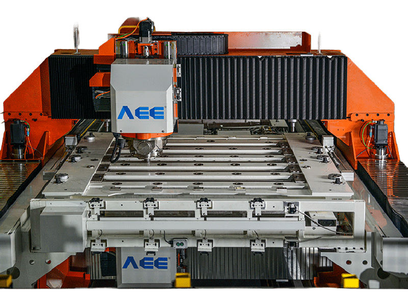
One machine in this class illustrates the point. AEE’s heavy-load model, the AEE FSW 100×100/2, is rated for 100 mm single-side aluminum and 35 mm single-side copper, or 190 mm when the joint is welded from both sides. Its spindle runs to 1000 rpm with 872 Nm and 105 kW, and the head carries 200 kN in Z and 100 kN in X over a 3000 mm by 8000 mm table. The structure is a double gantry with a hydraulically cooled spindle, and the control supports force and position control with data acquisition, laser tracking and weld monitoring.
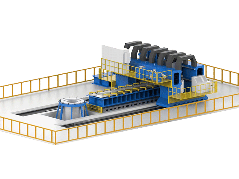
Those figures describe one configuration, not a limit for the process. A 60 mm aluminum part may need less force if the tool, joint and preheat allow it, and a 40 mm copper part may need more. The useful question is always what the intended tool and parameters require at your condition.
How Welding Copper Plate Differs from Aluminum
Copper moves the same process into a different regime. It conducts heat away from the stir zone much faster than aluminum, and the temperatures needed to soften it sit far higher, so heat generated at the tool leaves the weld before it has softened enough material through the full section. The result is a narrow window in which the surface looks properly consolidated while the root is still cold and unmixed.
Four responses follow from that mechanism. Axial force and torque rise for the same thickness, which pushes the equipment up a class. The tool needs a material that keeps its hardness at higher temperature. Preheat or an insulating backing plate stops the anvil from draining heat out of the root. Traverse speed falls, because the energy per unit length still has to come from somewhere.
Tool life is the sharpest practical difference. Welding aluminum with hot-work tool steel is a mature production routine with predictable wear. Copper consumes tools much faster, and cost per metre of weld becomes a real line in the process economics rather than a rounding item. That changes how you plan tool changes, spares and tool management, and it should be part of the quotation comparison rather than discovered during ramp-up.
The thickness ceiling reflects the same physics. A heavy-load machine rated for 100 mm aluminum is typically rated around 35 mm for copper in a single pass, with double-sided welding used to go beyond that. Welding from both sides halves the depth each pass must stir, at the cost of turning the part over, realigning it and introducing a second thermal cycle into the same joint.
Where copper meets aluminum, an additional limit appears that the machine cannot solve, namely the intermetallic layer that grows at the interface. Keep heat input and tool geometry tied to the intermetallic thickness the joint can tolerate, and treat any aluminum-to-copper procedure as something to qualify rather than transfer.
Thick copper work often ends where copper meets aluminum, and that interface brings limits the machine cannot remove. <Customized Dissimilar Material Welding Manufacturers in China> covers customized dissimilar material welding, including how such joints are approached in production.
Which Tool Geometry Works at 100 mm
At this thickness the tool is the part most likely to fail first, and the failure is usually the pin rather than the shoulder. A long pin has to transfer torque over a length that encourages bending, and it has to move plasticized material from the root to the crown without leaving a void behind. Smooth pins drag; threaded and fluted profiles pump material and reduce the torque needed for the same stir. The pin length must cover the section plus a small penetration allowance, and every extra millimetre of length increases bending load.
Shoulder diameter is a separate decision with a real trade. A larger shoulder generates more heat and forges a wider crown, but it raises axial force and widens the heat affected zone. On thick plate, shoulder heat is generated far from the root, so the pin has to carry the heating duty and the shoulder mainly contains the material. Matching the two is what a tool development trial is for.
Stationary shoulder tools separate the functions entirely. The shoulder slides on the surface without rotating while the pin rotates alone, which lowers heat input, produces no flash and leaves no thinning of the plate. The configuration suits thick sections and materials that do not conduct heat well, and our specification covers it to 110 mm in aluminum. The trade is speed and contact wear, and the non-rotating shoulder also changes the fixture design because that surface must be controlled like a sliding contact.
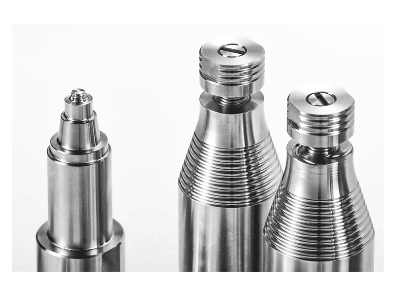
Self-reacting bobbin tools solve the backing problem instead of the heat problem. Two shoulders clamp the workpiece from both sides, so no rigid backing is required and lack of penetration at the root disappears by construction. The limitation is thickness, with the current range at roughly 3 mm to 20 mm, which rules it out for 100 mm plate but makes it attractive for long hollow profiles.
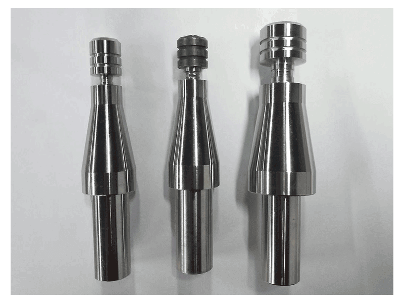
Retractable tools exist for a different reason, which is the exit hole. When a weld closes on itself, the pin is withdrawn into the shoulder and plasticized material fills the cavity. Whether that refill works at 100 mm depends on the volume of material available and on the tool design, so ask for evidence at your thickness rather than assuming the option transfers from thin work.
Tool material follows temperature. Hot-work tool steel covers aluminum and magnesium in most production settings. Copper, titanium and steel push the tool into nickel-based alloys, tungsten carbide or PCBN, and the choice interacts with the machine, because a tougher tool allows higher force and a harder tool demands more of the spindle.
Tool choice and the holder that carries it are normally decided together, because the interface determines how much torque reaches the pin. BT40 holders suit the lower torque range, while the heavy end moves to BT50 and BT60, and runout at the interface affects both weld quality and tool life.
Tool choice and the holder that carries it are normally decided together, since the interface determines how much torque reaches the pin. <AEE provides customer with optional features FSW tool> covers the optional features available on FSW tools.
Spindle Torque and Cooling at Low Rotation Speed
Power, torque and speed are locked together by one relationship, where P is shaft power in watts, T is torque in newton metres and n is rotation speed in revolutions per minute:
P = T × 2πn / 60
Running the numbers on a heavy-load spindle shows how the three ratings should relate. At 872 Nm and 1000 rpm, angular velocity is 2π × 1000 / 60, or about 104.7 radians per second, so the shaft delivers roughly 91.3 kW. That sits just under a 105 kW rating, which is the sensible relationship, since the motor keeps headroom over the torque it must deliver at maximum speed.
The check is worth applying to any data sheet. If a machine claims a high torque and a high speed from a small motor, one of the figures is a short-term peak and the machine will not hold both at once. Ask which pair is continuous.
Cooling becomes a load-path issue at this power level. A 105 kW spindle needs hydraulic cooling, and the thermal growth it produces moves the tool relative to the plate over a shift, which is why a warm-up routine and a reference check belong in the operating procedure. Long pins can also be cooled through the tool itself, a feature we build into double-head production lines where the pin runs continuously for long passes. Grease and oil lubrication are both used, and the choice affects maintenance intervals more than welding behaviour.
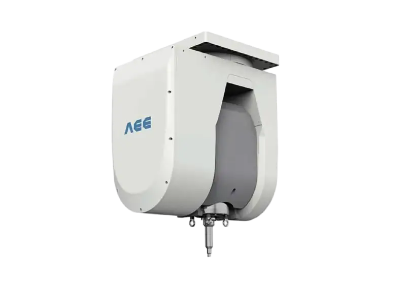
The spindle range behind these machines runs from a 12 kW unit for 1 mm to 8 mm work up to a 105 kW unit for 2 mm to 100 mm work, with the tool holder interface moving from BT40 to BT60 as torque climbs. Selecting inside that range is a question of the thickest section and the hardest alloy you intend to run, not of the largest number available.
Fixtures, Backing Support and Heat Flow in Thick Plate
The fixture completes the load path, and at 200 kN it is not a detail. Clamping has to resist the traverse force and the torque reaction, which means hydraulic clamping with a defined sequence rather than manual toggle clamps, and clamps must sit outside the weld path and outside the tool clearance. On thick plate the clamping force is large enough that the clamp layout itself influences distortion, so the sequence matters as much as the pressure.
The backing anvil has to be flat, rigid and hard enough to survive years of forging load without dishing. Any deflection in the anvil shows up as inconsistent penetration, and any wear groove shows up as a surface mark on the root side. For aluminum the anvil also acts as a heat sink that changes the cooling rate at the root; for copper, an insulating backing or preheat may be needed to stop the same effect from removing heat the process cannot spare.
Start and stop behaviour deserves its own provision. Thick sections need run-on and run-off tabs long enough for the force to stabilise before the tool reaches the joint, and long enough for the pin to exit without leaving a crater in the part.
Two Ways to Weld Both Sides
The first is a turn-over pass on a heavy-load machine, welding one side, turning the part, realigning and welding the other, which is how the 190 mm double-side figure is reached. The second is a double-head machine that welds both sides in one setup. The double-head approach removes the handling and the realignment error, and it runs at higher speed with spindles up to 6000 rpm, but its simultaneous double-sided rating is much lower, at 8 mm in the specification we build, so it serves a different part family.
Keyhole handling closes the section. A thick closed contour cannot be plugged economically, so the options are a run-out into a sacrificial extension, a retractable tool where the refill volume can be managed, or a design change that puts the weld start outside the finished part.
How to Specify and Qualify a Heavy-Load Machine
Most purchasing errors at this thickness happen in the RFQ, before any machine is compared. A request that names a table size and a thickness but leaves the force basis, the tool and the acceptance standard unstated will produce offers that cannot be compared, and the lowest price may come from the machine that cannot hold the load through the pass.
Fields to Put in the RFQ
| RFQ field | What to request | Why it matters |
|---|---|---|
| Alloy and temper | Exact designation and temper for both sides of the joint | Flow stress and thermal conductivity change the force needed, and a trial on another temper does not transfer |
| Thickness and joint | Single-side thickness, joint type, gap tolerance | Sets pin length, tool design and the force class, and a lap root behaves differently from a butt root |
| Force basis | Axial force at your welding condition, with the traverse during which it is held | A machine that reaches 200 kN at standstill may not hold it while moving through the pass |
| Backing and fixture | Anvil material, flatness, clamp layout, access to both sides | The reaction path decides whether force reaches the floor or deflects the plate |
| Acceptance basis | Standard, part and edition, quality level, NDT method and extent | A sound weld is not an acceptance criterion, and sectioning 100 mm plate is expensive |
| Site and utilities | Footprint, mass, foundation, crane, power, compressed air | A 120 t machine needs a designed foundation and a lifting plan before it ships |
Two fields do most of the work. The force basis separates a machine that holds load during traverse from one that touches a number on a data sheet, and the acceptance basis decides how much testing you will pay for on every production run. Tooling and consumables rarely appear in a machine quotation even though they are the largest running cost in copper work, so ask separately for tool material, expected metres per tool, regrind or replacement policy and spare lead time.
What a Trial Weld Proves and What It Does Not
| Record | Method context | Responsible use | Do not infer |
|---|---|---|---|
| Full-thickness macro section | One tool, one parameter set, one plate lot | Confirms penetration and reveals gross internal flaws at that condition | That the parameter window tolerates normal production variation |
| Bend or tensile coupon | Coupon cut from a qualified trial and tested to the agreed method | Shows joint strength for that configuration and test method | That a different temper or thickness reaches the same strength |
| Phased array ultrasonic scan | Procedure and operator defined, surfaces prepared, scan volume stated | Detects planar flaws in the scanned volume at the stated sensitivity | That flaws below the stated sensitivity are absent |
| Tool wear measurement after a fixed length | Same tool material, alloy and parameters as production | Indicates tool life for that combination | That copper tool life matches aluminum tool life |
| Machine force trace during the pass | Force control active and logged at production settings | Shows whether the machine held the set force through the pass | That the same force setting is correct at another thickness |
Those records belong to the trial they came from. A demonstration on 6082 plate is not evidence for 7075 forging stock, and a copper trial run with preheat does not describe the same plate welded cold. Ask the supplier to state, for each record, what it covers and what it leaves open.
Site and Utility Requirements
Layout is decided before the machine arrives. The heavy-load class needs a footprint around 25 m by 8 m and a machine mass near 120 t, with a foundation designed for the load path rather than for the static weight alone. Crane capacity for head assembly and tool changes, compressed air at 0.6 MPa and 1 cubic metre per minute, and power for a 105 kW spindle plus servo drives and cooling all belong on the site drawing. Ambient temperature swings of a few degrees show up in force stability on a machine of this size, so isolation from doors and yard traffic is worth planning.
Budget the installation rather than the machine alone. Civil works, rigging, power and cooling, commissioning, training, tooling inventory and the trial welds all sit around the machine price, and at this mass the civil work is not a rounding error.
Send the Thickness and Alloy Before You Compare Machines
Machine comparisons at this thickness are meaningful only against a defined part. Send the alloy and temper, the single-side thickness, the joint type, the part envelope, the annual metres of weld and the acceptance standard your customer applies, and we can answer with a configuration, the force and tool combination that suits it, and a trial plan on your material instead of a general offer.
A trial on your own plate is the only reliable way to confirm that a rated force and a chosen tool produce the section you need, and it costs far less than finding the gap after installation.
Email [email protected] or call +86 18325808715 to start that review. Include a drawing or a sketch with the weld position marked, because the backing and clamping arrangement depends on access to both sides of the joint.
FAQ
What is the maximum thickness a heavy-load FSW machine can weld?
On aluminum, the heavy-load class is rated to 100 mm in a single pass and to about 190 mm when the joint is welded from both sides. On copper the single-side figure is lower, typically around 35 mm, because copper drains heat from the stir zone much faster and the tool must survive a higher temperature. These are machine ratings rather than process guarantees. The thickness you can actually weld depends on alloy, temper, joint type, tool design and acceptance standard, and belongs in a trial on your material.
Can copper plate be welded thicker than 35 mm?
Beyond the single-side rating, the usual route is two passes, one from each side, so each tool stirs only half the thickness. That works, but it changes the fixture, doubles the handling and puts a second thermal cycle into the same joint. Preheating thick copper can reduce the force required, which helps the machine and complicates distortion control. Ask for a trial at your thickness before accepting a double-sided procedure, because the rating on paper and the welded section are different things.
Is a 200 kN machine always required for 60 mm aluminum?
No. Axial force depends on shoulder diameter, pin design, alloy, temper, preheat and travel speed, not on thickness alone. A 60 mm part welded with a stationary shoulder or with preheat may need less force than the same thickness welded with a conventional tool at high travel speed. The useful question is what the intended tool and parameters require at your condition, and the supplier should state that force and demonstrate it rather than quoting the machine maximum.
How do you control tool wear in thick-section production?
Measure it instead of waiting for a failure. Record metres welded per tool, inspect pin and shoulder at fixed intervals, and watch spindle torque and power for a slow rise at constant parameters, which usually means the tool geometry has changed. Set the wear limit by the weld quality you need, not by the point where the tool breaks. In copper this routine matters more than in aluminum, because tool consumption is higher and cost per metre becomes part of the process economics.
If you’re interested, check out these related articles:
AEE attend 13th International Symposium on FSW in Kyoto, Japan on 21 – 23 May 2024
Refill Friction Stir Spot Welding (RFSSW)
Customized Dissimilar Material Welding Manufacturers in China