
Extra-Length FSW Machines for 10m+ Rail and Marine Profiles
Table of Contents
- What Changes When the Weld Passes 10 m
- Which Profile Lengths Justify an Extra-Length Machine
- Machine Configurations for Long Straight Profiles
- Single-head extra-length configuration
- Double-head production line
- Rail Body Panels, Floors and Traction Beams
- Marine Decks, Stiffened Panels and Superstructures
- Clamping, Fixturing and Thermal Control Across a 15 m Seam
- Clamp pitch and force
- Backing and reference
- Thermal growth management
- Sequencing
- What the Accuracy Specification Proves About a Long Weld
- Specifying an Extra-Length FSW Machine
- Plan Your Longest Seam Before You Commit
- FAQ
- How long a seam can a friction stir welding machine produce?
- Can an extra-length machine weld hollow extrusions without a backing plate?
- What floor space and foundation does a 16 m machine need?
- Does a long seam weld as strongly as a short one?
An extra-length FSW machine is not a standard machine fitted with a longer bed. Once a seam passes roughly 10 m, the limiting factors move away from spindle power and into structural behaviour: a gantry that must hold axial force at the far end of a 16 m stroke, a fixture that must keep a hollow extrusion flat while the plate expands, and a tool that runs for hours in one programme. Rail and marine fabricators usually meet this problem on the first long panel, when the two ends of a seam measure differently from the middle. What follows sets out where the machine envelope really ends, which configuration fits which profile family, and what to put in a specification so acceptance is measured rather than assumed.
What Changes When the Weld Passes 10 m
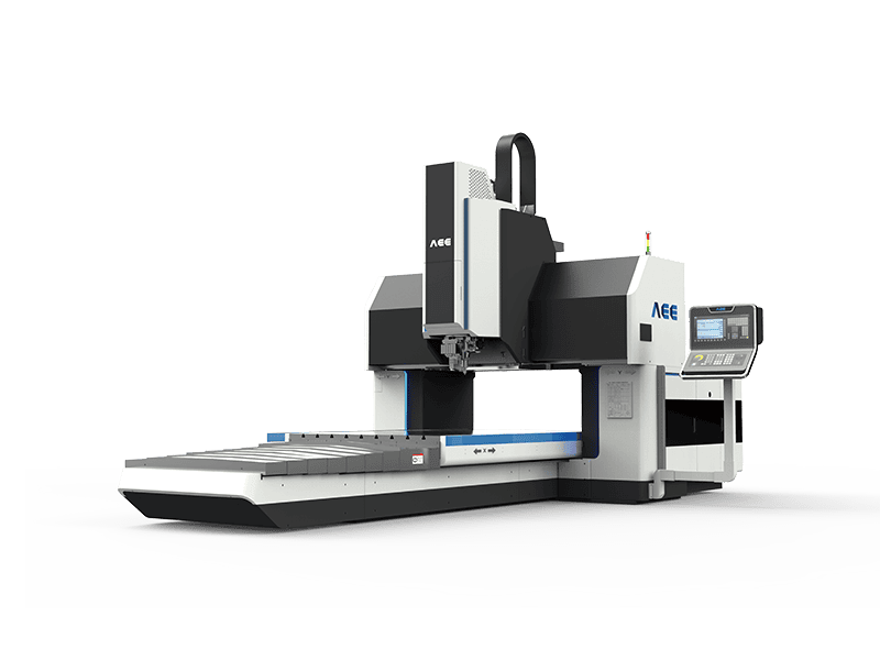
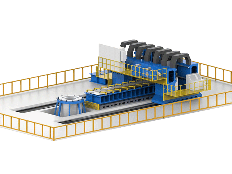
Short-seam FSW is dominated by the tool and the parameters. Long-seam FSW is dominated by the machine frame. Over 15 m of travel, the reaction force passes through a column and beam at changing positions, so stiffness that is adequate at the near end may deflect at the far end. A machine built for this duty carries mass in the structure deliberately: a supplied extra-length model weighs 75 t on a 20,000 mm by 7,000 mm by 3,100 mm footprint, and that mass is there to keep the tool path stable, not to add prestige to the datasheet.
Thermal movement is the second effect. Aluminium expands by about 23 µm per metre per kelvin, so a 10 K rise across a 16 m profile moves the far end by roughly 3.7 mm. No axis accuracy compensates for that automatically, because the workpiece is moving relative to the fixture as the seam is welded. What manages it is a reference and a compensation strategy: laser seam tracking that follows the joint rather than the drawing, force control that holds axial load when the plate lifts, and a fixture designed to let the profile grow in one direction instead of buckling.
Tool duty is the third. A 12 kW, 4000 rpm spindle holding 30 kN of axial force for a 14 m pass accumulates heat in the tool and holder in a way a 1 m pass never does. Tool wear over a long seam shows up as a gradual change in flash formation and shoulder imprint, which is why data logging of force and torque matters more here than on short work.
Which Profile Lengths Justify an Extra-Length Machine
The decision is not “how long can the machine travel” but “how long is the seam before a restart is acceptable”. A gantry machine with a 4 m stroke can weld a 16 m panel by indexing the workpiece, but every index creates a stop and restart in a structural weld. Each restart means a potential void at the termination, extra inspection, and a procedure that must qualify the restart condition. If a plant produces a steady mix of 10 m to 18 m straight profiles, a dedicated long machine removes that restart from the process entirely.
Three inputs settle the question. The length distribution of real production, not the maximum ever quoted, decides the stroke. The number of identical parts per shift decides whether a single-head machine or a double-head line is appropriate. Floor space and foundation condition decide whether an extra-length machine is installable at all, since a 20 m machine needs 20 m of usable building length plus loading and unloading zones, and a level, isolated foundation rather than a slab shared with press traffic.
For plants whose lengths stay under 4 m and whose part family changes often, a repositioned gantry remains the more flexible choice, and the capital goes further.
Machine Configurations for Long Straight Profiles
Long-profile work is served by several distinct architectures, and they are not interchangeable.
Single-head extra-length configuration
A single head on a long rigid bed handles straight seams from one side and keeps the process simple. A supplied model of this type, the AEE FSW 8×160/1 built by Aerospace Engineering Equipment (Suzhou) Co., Ltd., lists a 16,000 mm X-axis stroke with a 6,600 mm by 1,200 mm working table, a maximum welding thickness of 8 mm, X and Y feed rates of 10 m/min, positioning accuracy and repeatability of 0.03 mm on all three axes, and a 12 kW, 112 Nm spindle with 30 kN maximum Z-axis force. The machine performs 1D linear welding at any spatial position and carries automatic starting-point tool setting, constant-pressure control, laser tracking and parameter data acquisition. Read the stroke and the table as two separate numbers, because the seam length the machine can reach is set by the stroke while the support available under the seam is set by the table, and the two are rarely equal.
Double-head production line
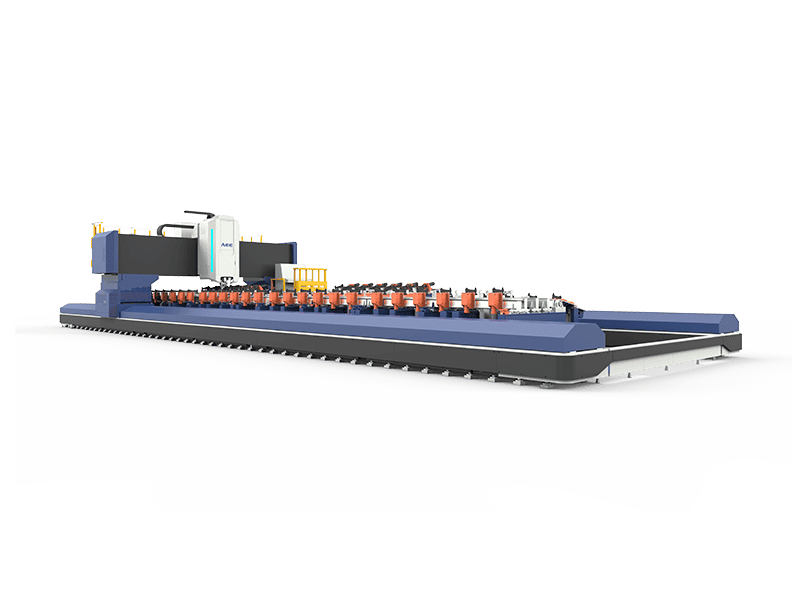
Where volume justifies automation, two heads on a moving gantry weld both sides of a long profile in one pass. A supplied fully automatic double-head line runs to 18,500 mm maximum weld length and 3,500 mm maximum plate width, over a 1.2 mm to 16 mm thickness range, with water-cooled pin tools and automatic handling from feed-in through welding to cutting. The trade is clear: a dedicated line gives short cycle time and repeatable clamping, but its fixtures and programs are built around a product family, and changeover to a new section is an engineering task rather than a parameter edit.
| Configuration | Typical working envelope | Structure and mass | Good fit | Constraint to plan for |
|---|---|---|---|---|
| Single-head extra-length | 16,000 mm X stroke, 6,600 mm by 1,200 mm table, 8 mm maximum thickness | Long rigid bed, 75 t, 20 m by 7 m footprint | Straight seams on long extrusions and panels welded from one side | Stroke exceeds table support, so long work needs support planning and a defined reference |
| Fully automatic double-head line | Up to 18,500 mm weld length, 3,500 mm plate width, 1.2 mm to 16 mm thickness | Twin-head gantry with automated handling | High-volume long straight profiles in rail and shipbuilding | Fixtures and programs are product-family specific |
| Gantry with large table | 4,000 mm X stroke, 2,500 mm by 4,000 mm table, 25 mm maximum thickness | Fixed gantry, 30 t, 31 kW spindle | Wide panels, two-dimensional seams, thicker plate | Seams beyond the stroke need workpiece indexing and a qualified restart |
| Heavy-load double gantry | 10,000 mm X stroke, 3,000 mm by 8,000 mm table, 100 mm aluminium and 35 mm copper single side | 120 t, 200 kN Z-axis force, 105 kW spindle | Thick structural members in marine and heavy rail | Foundation load, and slow Z feed of 1 m/min shapes cycle time |
Rail Body Panels, Floors and Traction Beams
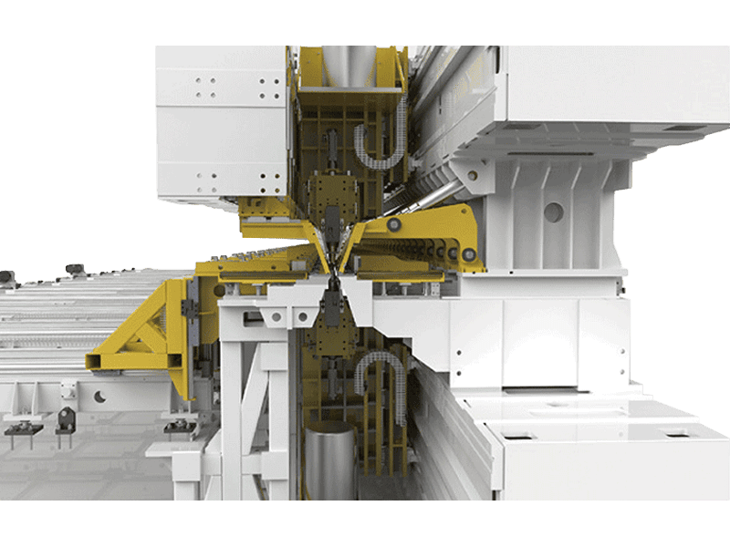
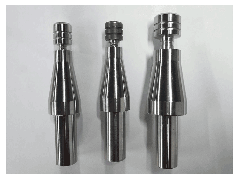
Rail structures are mostly hollow extrusions, and hollow sections change the tool decision. A conventional pin tool needs a rigid backing under the seam, which a closed hollow profile cannot offer. The bobbin tool solves this by turning the problem into a two-shoulder process: a second rotating shoulder replaces the backing plate and welds both surfaces at once. A supplied bobbin tool covers 3.0 mm to 20.0 mm in 4XXX, 5XXX and 6XXX alloys and high-strength grades, and removes root-side incomplete penetration as a defect class because there is no root to leave unfused.
For roof and side-wall panels assembled from several extrusions, the practical difficulty is sequencing. Welding every seam in one direction pulls the panel progressively to one side, and the accumulated contraction cannot be recovered by clamping alone. Fabricators usually alternate seam direction and work from the centre outward so contraction is balanced about the panel centreline. Traction beams and floor panels with thin walls create a different constraint: the shoulder must not thin the section. A stationary shoulder tool separates the functions, with the pin rotating while the shoulder slides, and a supplied unit covers 1.0 mm to 110.0 mm aluminium with no flash and no workpiece thinning, which suits floors and other thin-wall parts where a rotating shoulder would over-plasticise the surface.
Tool options change what a long seam can achieve at its edges, and some of those features are options rather than standard supply. <AEE provides customer with optional features FSW tool> covers optional features offered on friction stir welding tools.
Marine Decks, Stiffened Panels and Superstructures
Marine work differs from rail in alloy and thickness. Decks and superstructures are commonly built from 5083 or similar 5XXX grades, which are not heat-treatable and therefore do not soften in a heat-affected zone the way a 6XXX extrusion does. That sounds easier and often is not: the same alloy family is used at 5 mm to 25 mm and above, and the axial force required climbs with thickness faster than spindle speed does.
That is where machine class separates from machine length. A heavy-load double gantry with 200 kN of Z-axis force and a 105 kW spindle covers 100 mm aluminium and 35 mm copper from one side on a 3,000 mm by 8,000 mm table. A 12 kW long-stroke machine rated to 8 mm does not, however long its travel. Matching the two numbers, seam length and section thickness, before anything else prevents the most expensive specification error in this category.
Stiffened panels add a distortion problem. Longitudinal stiffeners welded to a plate create a T-joint thermal gradient that bows the plate if welding proceeds continuously along the stiffener. Intermittent sequences and chill bars under the plate help, and the fixture has to allow the plate to contract without lifting off the backing. Where a deck or superstructure connection pairs aluminium with steel, the constraint changes from heat input to intermetallic control at the interface.
Deck and superstructure connections sometimes pair aluminium with steel, which shifts the problem from heat input to intermetallic control at the interface. <Customized Dissimilar Material Welding Manufacturers in China> covers customised dissimilar material welding programmes.
Clamping, Fixturing and Thermal Control Across a 15 m Seam
A long seam fails at the fixture before it fails at the machine. Three fixture decisions carry most of the risk.
Clamp pitch and force
Clamping must hold the joint closed against the forging force without crushing a thin wall. For a 3 mm panel, dense low-force clamping or vacuum fixturing distributes load; for a 20 mm structural section, fewer higher-force clamps are adequate. A working rule is that clamp pitch should be short enough that the profile cannot lift between clamps under full axial force, which in practice means the pitch is set by the stiffness of the section, not by a standard spacing.
Backing and reference
The backing bar sets the weld plane and takes the reaction. Its groove depth, venting and wear condition change the seam over thousands of metres, so the bar is a consumable item with an inspection interval rather than a permanent part of the bed. On thin sections, an anvil with insufficient venting produces root marking that appears only on the last panels of a shift.
Thermal growth management
Because a 16 m aluminium profile moves several millimetres over a normal shop temperature swing, the fixture should locate the profile at a fixed datum and allow growth away from it, and measurements should be referenced to a stated part temperature. Welding a cold profile in a cold shop and inspecting it warm is a common source of apparent straightness failures that are really measurement artefacts.
Sequencing
Two further points decide the outcome. Run-on and run-off tabs keep the start and end of a structural weld out of the finished part, where the tool is least stable. And on a double-sided machine, welding both sides simultaneously balances the thermal field through the thickness and reduces the bowing that appears when one side is completed first.
What the Accuracy Specification Proves About a Long Weld
Machine accuracy figures are frequently read as weld quality figures. They are not, and the distinction decides how a purchase is evaluated.
| Record | Observed context | Legitimate use in your evaluation | Do not infer |
|---|---|---|---|
| 16,000 mm X-axis stroke on a supplied extra-length model | 1D linear welding along the full stroke | The machine can reach the seam length you need | That seam quality is uniform over 16 m without a mid-span acceptance test |
| 0.03 mm positioning accuracy and repeatability on X, Y and Z | Axis motion under stated test conditions | Axis control for tool positioning and repeatable start points | That weld straightness equals 0.03 mm, since distortion, fixture and thermal movement dominate |
| 8 mm maximum welding thickness on the extra-length configuration | Single-pass welding from one side | The thickness ceiling for that machine class | That a 12 mm rail extrusion can be welded on the same machine without a different structure |
| CE, ISO 9001 and EN 15085 listed for the model | Supplier quality and welding management systems | Screening of the supplier’s system and rail-related qualification | That your specific joint procedure is approved, because procedure qualification remains your responsibility |
| 18,500 mm rated weld length on a supplied double-head line | Line specification for long straight profiles | The envelope available for a dedicated production line | That a new profile section needs no new fixture or program |
The inspection that actually confirms a 15 m seam is a set of measurements, not a single number. Straightness is checked against the drawing tolerance with a laser tracker or taut wire at several stations along the length, with the part at a recorded temperature. Internal quality is checked by ultrasonic or phased array inspection along the full seam, with a macrograph from both ends and the middle to confirm nugget shape and any kissing bond at the root. Tensile and bend samples come from tabs welded under the same programme, and the force and torque logs from the machine are retained as production records, because a gradual drift in those traces predicts a tool change earlier than visual inspection does.
Specifying an Extra-Length FSW Machine
A specification that lists only stroke and spindle power leaves the expensive questions open. The fields below are the ones that change the machine architecture when they change.
| RFQ field | What to specify | Why it decides the machine |
|---|---|---|
| Length distribution | The real mix in metres, for example 6 m, 12 m and 16 m with quantities per shift | Sets stroke, table support and whether indexing is required |
| Section and joint type | Hollow extrusion, panel or plate; butt, lap or T-joint; 1D or 2D seam | Determines tool type and whether a backing support is accessible |
| Alloy, temper and thickness range | For example 6XXX extrusion and 5XXX plate, 1.5 mm to 8 mm | Sets axial force, spindle torque and heat input limits |
| Straightness and distortion tolerance | Millimetres over the full length plus the measurement method | Sets fixture design, sequencing and structural stiffness |
| Throughput | Welds per shift, target travel speed, load and unload method | Decides single head, double head, dual station and automation level |
| Acceptance test | Test pieces at the start, middle and end of the stroke, with NDT, macrograph and data records | Defines what acceptance means before the machine ships |
Two further items belong in the commercial documents rather than the technical table. The first is installation: a 75 t machine on a 20 m footprint needs a foundation designed for its mass and dynamic load, leveling to the supplier’s tolerance, and separation from traffic or press lines that transmit vibration. The second is the tool plan. A long seam consumes tool life in a predictable way, so the order should state how many tool sets ship with the machine, what the regrind or replacement interval is expected to be, and whether tool holders follow a standard interface such as BT40 or BT50 that the plant can source locally.
State the acceptance test as a physical witness. Three test pieces from along the same stroke, welded with the production fixture and the production programme, tell a buyer more about a long machine than any single datasheet figure, because they show whether the far end behaves like the near end.
Plan Your Longest Seam Before You Commit
Send the profile drawing, the alloy and temper, the length distribution, the joint type and the straightness tolerance you must hold. A feasibility run on your longest section answers the only question that matters before purchase: whether the seam you need sits inside the machine envelope you are being quoted, at the thickness and tolerance you actually produce. Aerospace Engineering Equipment (Suzhou) Co., Ltd. can review those inputs against an extra-length or double-head configuration and confirm which one the work requires. Email [email protected] or call +86 18325808715.
FAQ
How long a seam can a friction stir welding machine produce?
The travel defines the answer. Supplied extra-length machines reach a 16,000 mm X stroke, and dedicated double-head production lines are rated to 18,500 mm of weld length. Beyond the stroke, the workpiece must be indexed and the restart welded under a qualified procedure, which is a process decision rather than a machine limit. Check the stroke and the table support separately, since a long stroke with a shorter table changes how the work is set up.
Can an extra-length machine weld hollow extrusions without a backing plate?
Yes, with a self-reacting tool. A bobbin tool uses a lower shoulder in place of the backing plate and welds both surfaces at once, covering roughly 3 mm to 20 mm in common 4XXX, 5XXX and 6XXX alloys. The limit is section access: the lower shoulder must reach the underside of the joint. Closed hollow profiles suit it well, while a fully enclosed box with no lower access does not.
What floor space and foundation does a 16 m machine need?
A supplied extra-length model measures 20,000 mm by 7,000 mm by 3,100 mm and weighs 75 t, so plan for the machine footprint plus loading and unloading zones at both ends. The foundation must be designed for that mass and for the dynamic force of welding, leveled to the supplier’s tolerance, and kept away from vibration sources. Compressed air at 0.6 MPa and about 1 m³ per minute is the usual utility requirement.
Does a long seam weld as strongly as a short one?
Joint strength is set by the qualified procedure and the alloy, not by seam length. The length-specific risks are different: gradual tool wear, thermal drift along the stroke, and clamp release that lets a long part spring after welding. Those are controlled by recording force and torque, replacing tools on a measured interval, and sampling test pieces from the start, middle and end of the stroke rather than the middle alone.
If you’re interested, check out these related articles:
Refill Friction Stir Spot Welding (RFSSW)
AEE attend 13th International Symposium on FSW in Kyoto, Japan on 21 – 23 May 2024