
Swept FSSW: Larger Spot Weld Area, Higher Load Capacity
Table of Contents
- How Swept FSSW Expands the Spot Weld Area
- Why Larger Swept Spot Welds Carry Higher Loads
- Where Swept FSSW Fits in Aluminum Assemblies
- What Changes When You Move From Conventional to Swept FSSW
- Clamping and Lateral Force Rise
- Exit Hole Control
- Which Swept FSSW Parameters Need Early Confirmation
- What Do Engineers Ask About Swept FSSW?
- How is swept FSSW different from refill friction stir spot welding?
- Does swept FSSW eliminate the exit hole?
- What lap shear improvement can I expect from a swept path?
- Which machine configuration is required for swept FSSW?
- What is the main cycle time penalty for swept FSSW?
Swept FSSW is a practical upgrade when a conventional friction stir spot weld cannot reach the required lap shear strength in thin aluminum sheet. The approach moves the rotating tool along a programmed path after the initial plunge, expanding the bonded area beyond a single spot and redirecting load through a wider stir zone. In process development work on 6xxx series aluminum, I consistently see the highest value in joints where the spot diameter is constrained by access or flange width. This article explains how the swept path works, why larger bonded area changes joint strength, and which parameters need early confirmation before switching from conventional FSSW.
How Swept FSSW Expands the Spot Weld Area
Conventional FSSW creates one localized stir zone by plunging a rotating shoulder and pin into overlapping sheets and holding them under axial force. The joint diameter is set mainly by the shoulder diameter and the plunge depth. Swept FSSW adds a second stage. After the dwell period, the machine moves the full tool along a short linear, circular, or elliptical path while rotation and axial force remain active. The plasticized material is continuously stirred along that path, so the final bond is longer or wider than the tool footprint.
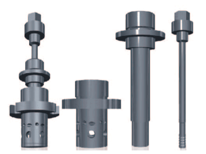
Three FSSW variants look similar at first pass, but the surface condition and load path differ in ways that matter for assembly design.
| Feature | Conventional FSSW | Swept FSSW | RFSSW |
|---|---|---|---|
| Spot area | One fixed spot | Expanded along a path | Refilled spot |
| Surface finish | Keyhole remains | Keyhole usually remains unless paired with refill | Flush, no keyhole |
| Load transfer | Narrow core | Wider bonded boundary | Full spot section |
The swept path is not the same as simply increasing the shoulder diameter. A larger shoulder calls for more forging force and can over-penetrate thin sheet, while a swept path with the same shoulder can extend the bond in a controlled direction. That matters when the available flange is long in one axis but narrow in the other, or when the machine force is already close to its limit.
For a visible-class surface with no keyhole, swept motion alone does not close the exit crater. <Refill Friction Stir Spot Welding (RFSSW)> covers how the sleeve and pin sequence backfills the cavity and preserves a flush joint surface, which is the usual route when a snapped-on cover or painted skin sits directly over the spot.
Why Larger Swept Spot Welds Carry Higher Loads
Lap shear strength in FSSW comes mainly from the area of fully bonded interface and the resistance of the stir zone to tearing out of the surrounding sheet. A single spot concentrates load transfer at its circumference. A swept path distributes the same load over a longer bonded boundary, so the peak stress at any one point drops before the joint reaches its limit. The most visible change in our test coupons is the failure location. Conventional spots often fail by pulling out a small plug or tearing along the weld edge. A well-executed swept path pushes the failure path outward, usually into the base sheet or the outer edge of the heat-affected zone.
The gain is not linear with path length. The start point and the exit crater do not carry the same load as the fully stirred middle of the path, and the trailing edge of the swept area can be less consistent after the tool passes. That is why a closed loop or an overlapping return pass often performs better than a single straight traverse of the same length. We look for a continuous, fully consolidated band, not just a longer visual mark on the sheet.
Where Swept FSSW Fits in Aluminum Assemblies
Swept FSSW is most useful where a joint must carry more than a single spot can transfer, but a continuous linear weld is difficult to reach or would require a full FSW fixture. Common candidates include brackets on extruded sections, door and closure flanges, seat structures, light-gauge reinforcements, and mixed-material stack-ups with limited flange width. It is also a practical study step for companies that already resistance spot weld or rivet aluminum and want to confirm whether friction stir spot welding can meet both load and cycle requirements.
For these applications, we evaluate the swept path direction against the load direction. The path should run across the highest tensile path, not extend the joint in a direction that sees little load. When the part geometry lets us align a linear sweep parallel to the applied tension, the joint is far more effective than the same welded area extending perpendicular to the load.
If your joint stack includes thin 6xxx sheet and a specified minimum lap shear that a single spot cannot meet without a larger machine, confirm the required swept path length and shoulder size before finalizing the BOM. Send your stack-up and target load to [email protected] and we will check the practical swept area against your flange width.
When the stack passes through a mixed material pair, the same swept path logic still holds, but the tool depth and intermetallic layer become the limiting variables. <Customized Dissimilar Material Welding Manufacturers in China> covers how custom tooling and process windows are developed for aluminum to copper, aluminum to steel, and other mixed stacks.
What Changes When You Move From Conventional to Swept FSSW
Swept FSSW is not a free process change on an existing cell. It requires a controller that can interpolate a path while maintaining axial force and tilt, and it adds a lateral force component that a single spot program does not see. Fixture stiffness becomes more important because the tool wants to push the workpiece sideways as it traverses. In many of the lightweight components we review, the original fixture was designed for vertical force only, so it must be checked for side load before swept trials.
Clamping and Lateral Force Rise
A swept path moves the tool while the pin is fully engaged in plasticized material. That produces a moving reaction force, not a static one. Clamps on either side of the intended path need to control sheet separation without pinching the free edge where material may be pushed ahead of the tool. For long sweeps on unsupported flanges, we add local supports behind the weld line or switch to a machine platform with better lateral rigidity.
Exit Hole Control
A standard swept path still leaves an exit cavity at the end of the tool stroke, and because the tool moves, the opening may be elongated rather than round. If that is not acceptable, the swept path should terminate in a sacrificial tab or be paired with a retractable or refill tool. Selecting this early changes the tool design and the machine requirements more than the weld path itself.
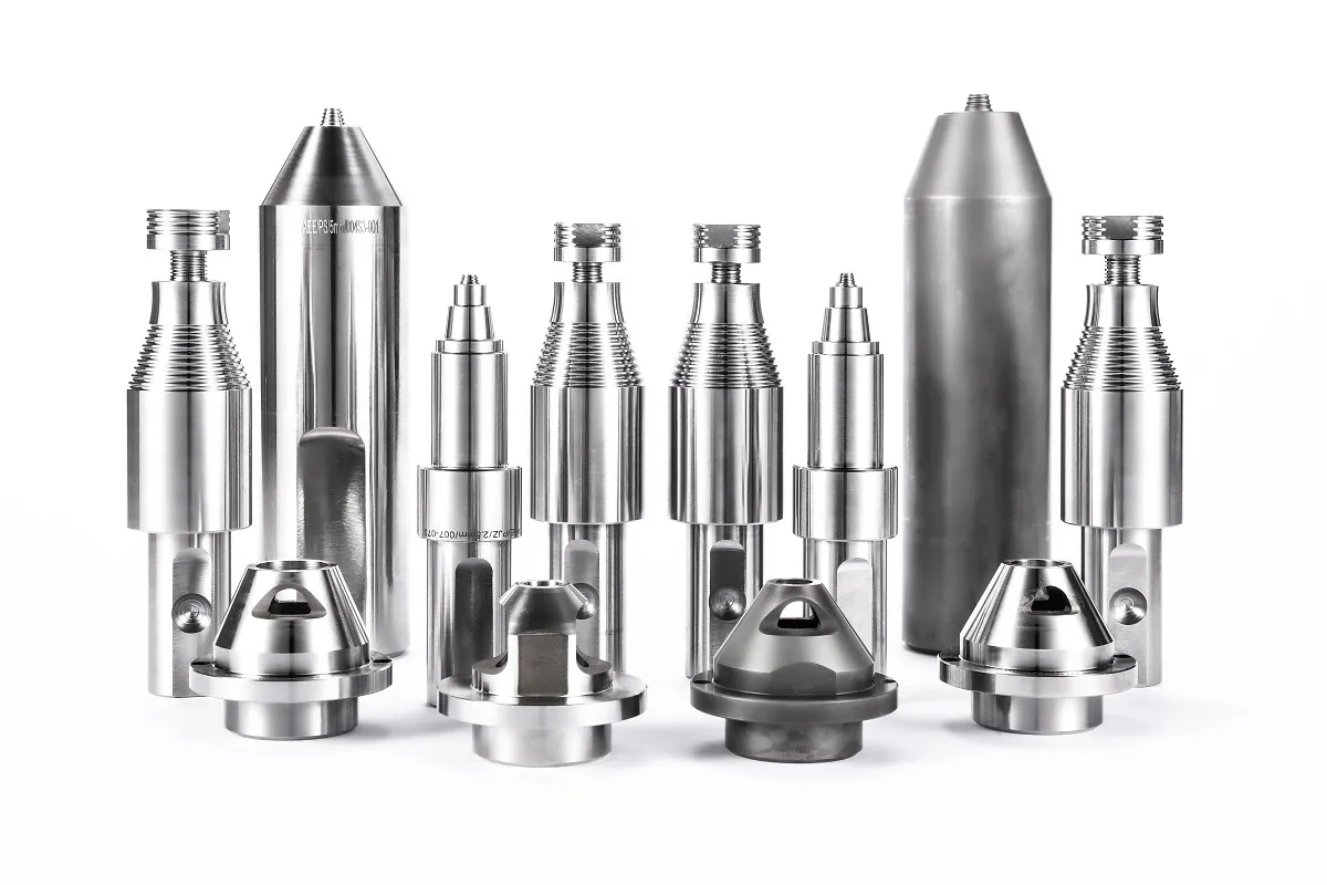
If the final swept tool needs a non-standard pin length, shoulder profile, or coating for a mixed stack, <AEE provides customer with optional features FSW tool> covers how these features are selected and tested before production release.
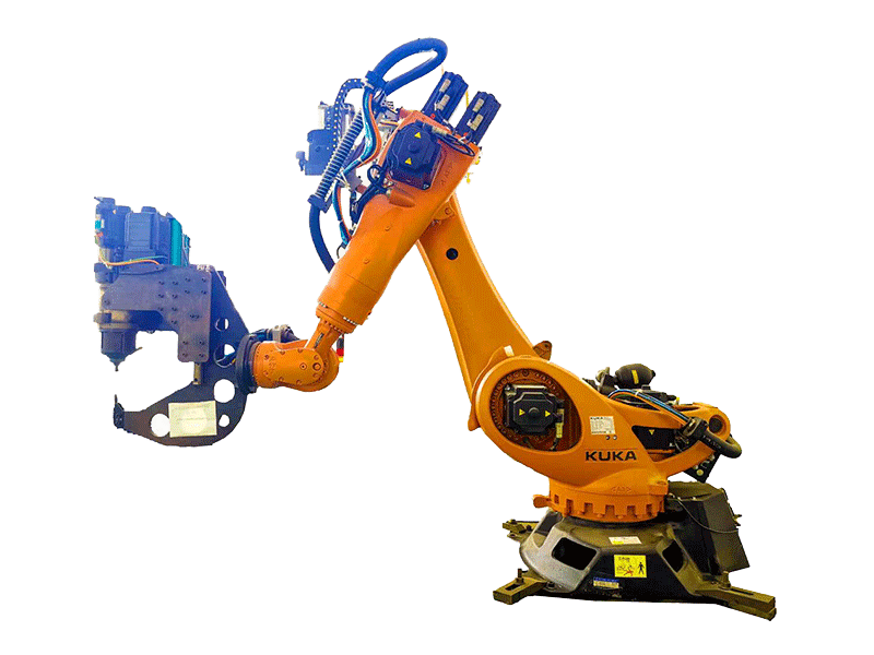
At AEE, the FSSW platform range includes both robot cells and desktop equipment. A robot cell has the flexibility for short swept paths inside a production line, while a desktop platform works for the operator-led process refinement that precedes series tooling. The machine choice affects the swept path quality mainly through stiffness, force control, and path interpolation, not through weld metallurgy.
Which Swept FSSW Parameters Need Early Confirmation
Before a swept FSSW tool is designed, five parameters should be fixed: sheet stack and temper, accessible flange width, required lap shear at minimum and typical thickness, path direction relative to load, and acceptable cycle time. If you leave any of these open, the tooling and fixture will both need to change later, and the load result may fall short even if the weld looks acceptable.
Machine force is another early filter. Swept FSSW does not usually increase peak axial force above a single spot, but it adds lateral force at the tool and can expose backlash or compliance in older machines. A machine with stiff axis control, a rigid spindle, and proper FSSW tooling usually handles the process. A general-purpose robot arm without force-controlled plunge will be harder to keep stable on a long swept path.
Send the material grades, stack-up thickness, and required lap shear to [email protected]. We will confirm whether a swept path can meet the load within your available flange width and what cycle time to expect. For urgent process trials, call +86 18325808715.
What Do Engineers Ask About Swept FSSW?
How is swept FSSW different from refill friction stir spot welding?
RFSSW uses moving sleeve and pin elements to refill the exit cavity and leaves a flush surface. Swept FSSW moves the whole rotating tool along a path to enlarge the bonded area and usually leaves a keyhole at the end of the path unless a refill or retractable feature is combined with it. Swept FSSW makes sense when more bearing area is the primary need. RFSSW makes sense when a flat, keyhole-free surface is the primary need.
Does swept FSSW eliminate the exit hole?
Not by itself. Many people assume that because the tool travels, the exit defect disappears. In practice, the final tool position still leaves a cavity, and it is often elongated by the sweep. If the part cannot accept any cavity, the path should end in a sacrificial tab, or the process should use a retractable or refill tool.
What lap shear improvement can I expect from a swept path?
It depends on path length, overlap, sheet thickness, and material temper. A short linear path can roughly double the effective bond width, but the actual lap shear gain is limited by the base sheet and the local heat-affected zone rather than by the weld area alone. The only reliable answer comes from cutting tensile coupons from the real stack and comparing failure location and peak load with a conventional spot.
Which machine configuration is required for swept FSSW?
The first question is not which machine, but whether the motion system can maintain axial force and tilt while traversing. A force-controlled FSSW machine with interpolated path control and a stiff fixture works for most short sweeps. A robot cell may be sufficient for shorter paths on open flanges. A dedicated CNC platform is better for tight cycle time, high volume, or long paths.
What is the main cycle time penalty for swept FSSW?
In the programs we support, a short linear sweep adds a few tenths of a second after the initial dwell, while a circular path or a path with a return overlap adds closer to a full second or more depending on traverse rate. The penalty comes from the traverse segment and any second dwell, not from plunging deeper. If your line rate has little buffer, share the target cycle time early. Send your stack-up, required lap shear, and cycle time target to [email protected] and we will confirm which path geometry fits within your line rate.
If you’re interested, check out these related articles:
AEE attend 13th International Symposium on FSW in Kyoto, Japan on 21 – 23 May 2024
Refill Friction Stir Spot Welding (RFSSW)