
Standard vs Customized FSW Machines: Defining Requirements
Table of Contents
- Where a Standard FSW Machine Ends and a Customized One Begins
- What Each Machine Family Already Covers
- The Four Requirement Groups That Decide the Build
- Part envelope, thickness and alloy
- Weld path, joint type and axis set
- Size, length and machine mass
- Throughput and fixture arrangement
- When a Standard Platform Is the Right Choice
- When Customization Pays for Itself and What It Costs
- Writing a Requirement Set That Suppliers Can Quote Against
- Checks That Confirm the Machine Matches the Requirement
- Send the Requirement Set Before You Compare Quotes
- FAQ
- Can a standard FSW machine be upgraded later if the part family changes?
- Do curved or 3D welds always require a custom build?
- How do I compare two quotes when one is standard and one is custom?
- What drives the price difference between a standard and a customized machine?
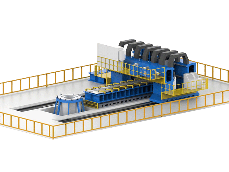
A standard FSW machine buys a catalogued envelope: a fixed table size, a fixed spindle class and a fixed number of axes. A customized FSW machine buys a structure built around one part family, together with the engineering work that decision carries. The build choice should not start with budget. It starts with four requirement groups: the part envelope, the weld path, the size and length of the part, and the throughput and fixture arrangement. Those four decide whether any catalogue platform can physically reach the joint and hold it. Projects that arrive convinced they need a custom build often need a standard platform with a project fixture and a matched tool; a smaller number genuinely need new machine structure.
Where a Standard FSW Machine Ends and a Customized One Begins
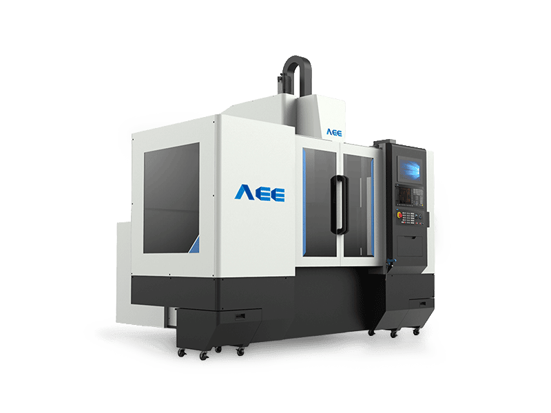
A standard machine is a platform whose structure, spindle class and axis configuration are defined and documented before your part exists. A customized machine is a platform where one of those three changes to suit the part. Size and price do not draw the line. A straight-profile machine with a 16,000 mm stroke and a heavy-load gantry rated for 100 mm aluminium are both catalogue products, and both sit far outside what a first-time buyer pictures when the word standard appears in a quotation.
The term is usually confused with the fixture. On most projects the clamping set, the backing support and the tool are built for one part family even when the machine is a catalogue item, and that is normal practice. What makes a build customized is a change to the force frame, the spindle interface, the axis count, the control integration or the automation content.
The mechanism behind the boundary is mechanical rather than commercial. The machine supplies axial force, spindle torque and structural stiffness at the weld; the fixture reacts those loads and holds the joint line. If a catalogued structure can deliver the load at the required accuracy and reach every point of the seam, the machine is standard. If it cannot, either the structure changes or the process does, and the second option is frequently the cheaper one.
That last point deserves a test before any custom enquiry is raised. A different tool design, a different tilt, a revised clamping sequence or a different pass plan sometimes brings an out-of-range part back inside the catalogue envelope. The reverse also happens: a part that looks ordinary turns out to need a different spindle class once the alloy and the joint preparation are stated.
What Each Machine Family Already Covers
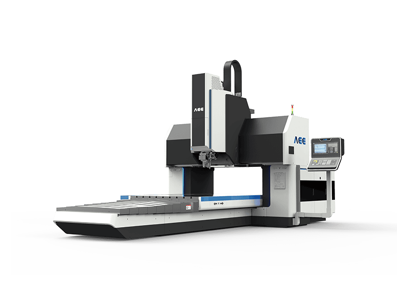
Catalogue ranges are wider than most buyers expect, so the first useful check is a comparison against published platform data rather than a request for a custom quotation. AEE’s catalogued platforms, used as the reference set here, run from a 600 mm by 1200 mm C-type table with 8 mm welding thickness to a 3,000 mm by 8,000 mm heavy-load gantry rated for 100 mm aluminium on a single side. Between those ends sit gantry platforms at 16 mm and 25 mm, 2D gantry platforms, an extra-length straight-profile machine with a 16,000 mm X stroke, and 3D platforms built around a swing head.
| Record | Method context | Responsible use | Do not infer |
|---|---|---|---|
| 8×10/2 C-type, 8 mm, 112 Nm, 30 kN | Catalogued 2D platform, 600 × 1200 mm table | Sets the lower bound of the catalogue range for thin aluminium work | That the 8 mm figure transfers to copper, or to a full-penetration seam with no sample weld |
| 25×40/1 gantry, 25 mm, 257 Nm, 60 kN | Catalogued 1D platform, 2500 × 4000 mm table | Large table and moderate thickness can coexist on one platform | That table area implies force capacity, or that a 1D platform follows a curved seam |
| 8×160/1 straight profile, 16,000 mm stroke, 8 mm | Catalogued long-seam platform, 6600 × 1200 mm table | Long welds are catalogued, so length alone does not force a custom build | That a long-stroke platform can be pushed into thick plate |
| 100×100/2 heavy load, 100 mm aluminium, 35 mm copper, 872 Nm, 200 kN | Heavy-load double gantry, 120 t machine | Shows the force and torque step that thick section requires | That a single-side aluminium rating carries to a curved path or an untested alloy |
| Spindle S064, 2 to 100 mm, 105 kW, 874 Nm | Spindle class data, BT60 interface | Spindle class is the first physical limit to check | That a spindle rating alone defines machine capability; the force frame must match |
Read the last column as carefully as the first. A catalogue thickness is a mechanical envelope tied to a qualified procedure, not a welding procedure in itself. A platform rated to 8 mm still needs a procedure written for your alloy, joint and thickness, and the heavy-load platform’s 100 mm aluminium figure drops to 35 mm for copper because the flow stress and process window are different.
Two consequences follow. First, a requirement that already sits inside a catalogued envelope gains nothing from a custom build except cost and lead time. Second, the same nominal label can describe very different machines. An 8 mm standard machine may mean 112 Nm and 30 kN on a C-type frame, or a different spindle class on a gantry platform, and the two behave differently at the top of the thickness range.
The Four Requirement Groups That Decide the Build
Four groups of information decide the build. Each one changes a physical part of the machine, so each one must be settled before two suppliers can quote a comparable price.
Part envelope, thickness and alloy
Thickness drives spindle torque and axial force, and the step is steep. The catalogue moves from 30 kN and 112 Nm at 8 mm to 200 kN and 872 Nm at 100 mm, because the tool has to stir a larger plasticised volume and the fixture has to react the resulting load. Alloy changes the same relationship: copper at 35 mm on the heavy-load platform demands the same force class as 100 mm aluminium, since higher flow stress narrows the process window and raises the load needed to maintain it.
Weld path, joint type and axis set
A straight seam runs on a 1D platform. A planar contour adds a rotary C-axis under the head or the table, which is why 2D platforms appear throughout the catalogue. A compound curve needs A and C motion together, with catalogued 3D platforms carrying A travel of plus or minus 100 degrees and C rotation of plus or minus 360 degrees. Curvature as such does not force a custom design; a head configuration, reach or force level outside the catalogue does.
Joint type matters here as well. A lap spot joint is a different machine category rather than a short seam, with its own kinematics and tooling family.
Spot welding is a separate build decision from seam welding, and the tooling follows that difference. <Refill Friction Stir Spot Welding (RFSSW)> covers the refill variant of friction stir spot welding.
Size, length and machine mass
Stroke and table size set the reach, and reach sets mass. Catalogue machines run from 6 t on a C-type frame to 120 t on the heavy-load gantry, and that range changes floor loading, foundation design, crane access and installation time. Buyers often settle thickness and path first and discover the foundation requirement late, when the civil work is already priced.
Throughput and fixture arrangement
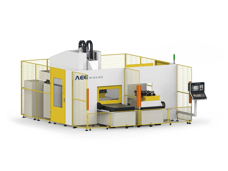
Cycle time decides how many stations and heads the machine needs. Where loading and unloading take longer than the weld itself, a dual-worktable platform or a double-head configuration does more for output than a faster spindle. A double-head machine welding 8 mm from both sides at up to 2.5 m per minute, or a dual-station platform with automatic tool change, addresses the handling share of the cycle instead of the welding share.
| Requirement group | What it changes on the machine | What to state in the RFQ |
|---|---|---|
| Thickness and alloy | Spindle class, torque, axial force | Thickness range per joint, alloy and temper, single or double sided |
| Joint and path | Axis set: 1D, 2D with rotary axis, 3D with A and C | Joint type, path drawing, curvature, tilt requirement |
| Part size and weld length | Stroke, table, gantry span, foundation load | Maximum part envelope, weld length per part, part mass |
| Throughput | Worktable count, head count, tool change, automation | Cycle time, annual volume, shift pattern, automation level |
| Accuracy and inspection | Control system, feedback, measuring capability | Positioning accuracy, repeatability, inspection method and acceptance |
| Site services | Power, cooling, compressed air, floor capacity | Available power, air supply at the required pressure, floor loading |
When a Standard Platform Is the Right Choice
A standard platform fits when the part sits inside a catalogued thickness class for its alloy, the seam is straight or planar, the weld length falls inside the available stroke, and the handling time is shorter than the welding time. Accuracy is part of the same test: catalogue positioning accuracy of 0.03 mm to 0.05 mm with repeatability around 0.03 mm covers most structural work, and an application demanding tighter control is arguing for a different machine rather than a different fixture.
The exclusion matters more than the inclusion, so read the right-hand column before the middle one.
| Condition | Standard platform | Do not choose standard when |
|---|---|---|
| Thickness within a catalogued class for that alloy | Yes, confirmed with a sample weld | The joint sits at the platform limit and no qualified procedure exists yet |
| Straight or planar seam | Yes, 1D or 2D platform with rotary axis | The seam needs continuous normal-axis control across a compound curve |
| Weld length within the longest stroke | Yes, straight-profile platforms cover long seams | The part exceeds the longest stroke and cannot be repositioned between passes |
| Handling time shorter than weld time | Yes, single worktable | Loading and unloading dominate the cycle and a second station is required |
| Stable part family for several years | Yes | The part family is expected to change inside the payback period |
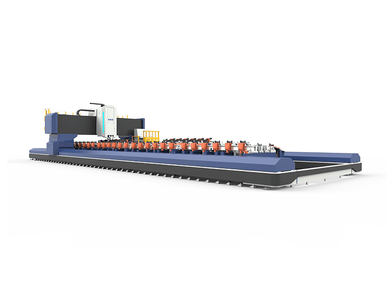
Long parts are the clearest case of a requirement that looks custom and is not. A straight-profile platform with a 16,000 mm X stroke and 2D capability covers rail body structures and long hollow profiles without new machine design, provided the thickness stays inside its 8 mm envelope and the part can be supported along its full length.
When Customization Pays for Itself and What It Costs
Customization earns its cost when a physical limit cannot be avoided: force beyond the heaviest catalogue frame, a head configuration the catalogue does not carry, integration into an existing line with specific loading, tracking and traceability requirements, restricted clamping access on a closed part, or an accuracy requirement outside catalogue figures. Each of those changes the machine itself, and no amount of fixture work substitutes for the change.
The cost side is broader than the machine price. A custom build carries non-recurring engineering, a longer programme, first-article validation, a spare parts position for one machine rather than a platform family, and a single-source dependency for support. The largest risk sits in the definition phase: a requirement changed after the structure is released costs far more than the same requirement changed in the enquiry. That is the trade. A catalogue platform moves risk onto the supplier’s proven design, and a custom design moves risk back onto the accuracy of your specification.
A common middle case is a catalogued platform with a different spindle class, a different table or an added rotary axis. The structure stays proven, the interface changes, and the cost sits between the two extremes. Sorting that case from a genuinely new design is the practical work of this decision.
Mixed-material parts often push a project toward a custom build because two alloys behave differently under one tool. <Customized Dissimilar Material Welding Manufacturers in China> covers customized dissimilar material welding work for buyers sourcing from China.
Writing a Requirement Set That Suppliers Can Quote Against
Quotes are comparable only when the requirement is written at the level of physical consequences. A vague line produces two prices that cannot be compared and a design change later that neither price anticipated.
Reject this RFQ line: “FSW machine for aluminium, 3 to 12 mm, table around 3 m, please quote.”
Replace it with a statement that fixes the physics: alloy and temper per joint, thickness range per joint type, joint configuration with a weld path drawing, maximum part envelope and weld length per part, part mass, required cycle time and annual volume, fixture concept and clamping access, positioning accuracy and inspection acceptance, and the point at which the weld procedure will be qualified.
Each line changes something on the machine. Thickness sets the spindle class, the path sets the axis count, the part mass and length set the structure and the foundation, cycle time sets the station count, and the inspection clause sets the control and measuring package. State all of them once and both suppliers quote the same machine, whether it comes from a catalogue or from a design office.
Thickness alone is not the specification. A 12 mm requirement on a 3 mm part family invites a heavier machine than the work needs, and it hides the joint type that actually decides the axis set.
Checks That Confirm the Machine Matches the Requirement
Verification starts before the purchase order. Ask for a sample weld on your alloy at your joint thickness with the proposed tool, then inspect the result by the method you will use in production: a macro section for penetration and nugget shape, hardness across the joint, and tensile results from a qualified test piece. A visual check alone confirms appearance, not joint quality.
At the factory acceptance test, verify the items that matter to your process rather than the items that are easy to measure. Axis positioning accuracy and repeatability against the quoted figures, spindle runout, force and torque calibration, the safety system, and the data logging you will rely on for traceability all belong in the acceptance document before shipment.
Documentation completes the check. Drawings, the spare parts list, control manuals, the qualified weld procedure and its supporting records, and the training plan should be agreed as deliverables, not left to handover. For a custom machine, the acceptance criteria should be written into the order at the same time as the technical specification, because a custom build is only as verifiable as the specification it was ordered against.
Send the Requirement Set Before You Compare Quotes
Send the alloy and temper for each joint, the thickness range per joint, the joint type and weld path with a drawing, the maximum part envelope and weld length, the part mass, the required cycle time and annual volume, the fixture concept and clamping access, the positioning accuracy and inspection acceptance, and the point at which the weld procedure will be qualified. That list is enough to say which requirements a catalogued platform already covers and which ones force a design change, so the comparison is between machines rather than between headings. Thickness alone is not the specification.
Aerospace Engineering Equipment (Suzhou) Co., Ltd
[email protected]
+86 18325808715
FAQ
Can a standard FSW machine be upgraded later if the part family changes?
A platform can take a different tool, a different fixture, and in some cases an added rotary axis or a different spindle class, within the limits of its force frame. What cannot be changed economically is the structure itself: a C-type frame rated at 30 kN does not become a 200 kN heavy-load gantry. If the expected change is thickness or force, buy the next force class up at the start. If the expected change is geometry, clamping or inspection, the platform usually absorbs it with a new fixture and a revised procedure.
Do curved or 3D welds always require a custom build?
No. Catalogued 3D platforms exist with A-axis travel of plus or minus 100 degrees and C-axis rotation of plus or minus 360 degrees, and they cover curved seams up to their rated thickness. The custom question is not curvature itself but whether the seam needs a head configuration, a reach or a force level outside those platforms. A gentle contour on a thin panel often runs on a 2D platform with a rotary axis, while a compound-curved thick section usually does not.
How do I compare two quotes when one is standard and one is custom?
Put both quotes against the same requirement list and check three items first: spindle class and rated force against your thickness and alloy, axis set against your weld path, and stroke against your longest weld. Then compare what is included, because fixture design, sample welding, procedure qualification, installation, training and the spare parts list are frequently priced separately. A custom quote that includes validation and a standard quote that excludes it are not the same offer, and the cheaper one can become the more expensive after the first design change.
What drives the price difference between a standard and a customized machine?
Structure mass, spindle class, axis count, control integration and the engineering work behind the design. Moving from a 6 t C-type frame to a 120 t heavy-load gantry is a change of an order of magnitude in material and machining, and adding a swing head, a second worktable, a second welding head or line integration adds cost at the same time. Non-recurring engineering and first-article validation belong in the comparison, and so does the spare parts position for a one-off build.
If you’re interested, check out these related articles:
AEE provides customer with optional features FSW tool
AEE attend 13th International Symposium on FSW in Kyoto, Japan on 21 – 23 May 2024
Customized Dissimilar Material Welding Manufacturers in China
Refill Friction Stir Spot Welding (RFSSW)