
FSW Spindle Selection by Material: Power, Torque and Speed
Table of Contents
- What the Three Spindle Ratings Actually Mean
- Why Material Sets the Torque Requirement Before Speed
- Material Groups and the Rating That Decides Each One
- Thickness Moves the Requirement More Than Alloy Grade
- When Higher Rotation Speed Stops Helping
- Tool Holder, Runout and the Interface Buyers Overlook
- Writing Spindle Requirements Into an RFQ
- Send the Weld Schedule Before You Compare Spindles
- FAQ
- Can a spindle deliver rated torque at its maximum speed?
- Which matters more for FSW, torque or power?
- Do I need a water-cooled spindle for production welding?
- Can one spindle cover both 2 mm sheet and 20 mm plate?
- Does the tool holder type affect which spindle I should choose?
An FSW spindle is bought on three numbers that rarely apply at the same moment: maximum rotation speed, rated torque, and motor power. Read as a set, they describe one operating curve. Read separately, they invite a specification error that only surfaces when a thick copper plate or a thin lid reaches the machine. FSW spindle selection begins by converting those three figures into the speed at which torque starts to fall, then matching that curve to the flow stress of the alloy and the thickness of the joint. Alloy grade changes the shape of the requirement, but thickness moves it further.
What the Three Spindle Ratings Actually Mean
Power, torque and rotation speed are linked by the shaft relation P = T × ω. In the units used on welding equipment, the working form is T (Nm) = 9550 × P (kW) / n (rpm). That single equation does two jobs. It converts a power rating into the torque available at any speed, and it reveals the speed at which the spindle runs out of torque.
A 12 kW spindle rated at 112 Nm and 4,000 rpm cannot deliver both figures at once. At 4,000 rpm, 12 kW corresponds to about 28.7 Nm. The full 112 Nm is reachable only up to roughly 1,023 rpm; above that point the drive holds constant power and torque falls in inverse proportion to speed. Every model in the AEE spindle series follows the same pattern, holding rated torque to approximately 1,000 to 1,150 rpm before the constant power region begins. That consistency is a design choice, not an accident of catalogue writing.
This behaviour is normal. A motor and its reduction stage are matched so the spindle can push a large tool through thick material at moderate speed, or a smaller tool at high speed with less torque. What matters to a buyer is knowing which side of that curve the actual weld will occupy.
Table 1. Six models from the AEE spindle series. The final column is calculated from T = 9550 × P / n and represents a power limit, not a mechanical rating.
| Model | Weld thickness (mm) | Max speed (rpm) | Power (kW) | Rated torque (Nm) | Torque at max speed (Nm, calculated) |
|---|---|---|---|---|---|
| AEE-S125 | 1 to 8 | 4,000 | 12 | 112 | 28.7 |
| AEE-S119 | 2 to 12 | 4,000 | 25 | 208 | 59.7 |
| AEE-S112 | 2 to 16 | 2,500 | 25 | 208 | 95.5 |
| AEE-S065 | 2 to 25 | 2,000 | 31 | 257 | 148.0 |
| AEE-S076 | 2 to 40 | 1,500 | 58 | 482 | 369.3 |
| AEE-S064 | 2 to 100 | 1,000 | 105 | 874 | 1,002.8 |
Where the calculated value at maximum speed exceeds the rated torque, as it does for the largest model, the mechanical rating is the binding limit and the drive has spare capacity. For the smaller models the reverse holds, and power limits what the spindle can do at its top speed.
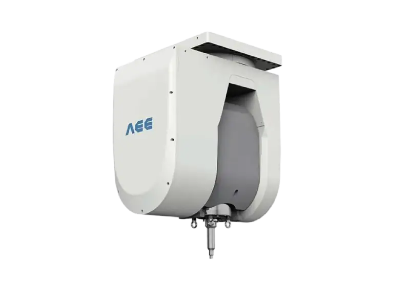
The practical consequence is a change in how quotations are compared. A supplier who quotes rated torque alone has described the low speed end of the curve. Ask instead for the torque available at the rotation speed the weld will actually run, and the answers become comparable.
Why Material Sets the Torque Requirement Before Speed
Torque is the spindle’s answer to the reaction the tool generates in the stir zone. As the pin and shoulder move through plasticised metal, the material resists, and the drive must overcome that resistance continuously. The size of the resistance depends on how much stress the alloy carries at the welding temperature, how much of the shoulder is in contact, and how fast the tool is translating.
Flow stress is the governing property. A high strength alloy that still carries significant stress at 400 to 500 °C demands more torque than a soft alloy at the same thickness. Temperature is what lowers that stress, which is why heat generation and torque demand are coupled: a process that loses heat to the fixture or the surrounding plate stiffens the material ahead of the tool and pushes the torque requirement up.
Thermal conductivity decides how much of the generated heat stays where it is needed. Aluminium conducts heat away reasonably quickly, copper far faster. In copper, the stir zone bleeds energy into the surrounding plate, the plasticised volume becomes harder to maintain, and the machine has to supply more axial force and more torque to keep the same weld quality. This is the single largest reason why copper and aluminium cannot share one spindle specification even at equal thickness.
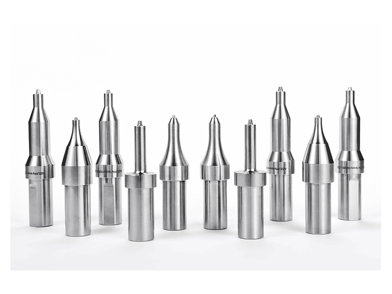
Tool geometry multiplies the demand. A larger shoulder increases the contact area and therefore the torque needed to rotate it, while improving containment of the plasticised material. A longer pin raises the volume of metal being stirred. A conventional tool with a threaded pin trades some additional torque for better material transport, which is often the right trade in thick sections. The consequence for spindle selection is that tool design and spindle rating are decided together, not in sequence. A spindle chosen without a tool drawing behind it is a guess.
Travel speed closes the loop. Faster travel reduces the heat input per millimetre, cools the stir zone, raises flow stress and increases the torque needed at that instant. A machine that welds comfortably at low travel speed can run out of torque when the same joint is pushed for cycle time.
Material Groups and the Rating That Decides Each One
Grouping alloys by what they demand from the drive is more useful than grouping them by series number, because two alloys from different families can impose similar loads while two from the same family can differ sharply in temper.
Table 2. What each material group loads, and which spindle attribute decides the outcome.
| Material group | What loads the spindle | Rating to verify first | Tool or process consequence |
|---|---|---|---|
| 6xxx aluminium | Moderate flow stress, forgiving window | Torque at the target travel speed | Conventional tool usually sufficient |
| 2xxx and 7xxx aluminium | Higher flow stress, narrow heat input window | Torque plus fine speed control at the low end | Heat input control matters more than peak power |
| Copper | Very high thermal conductivity pulls heat from the stir zone | Axial force capacity and sustained torque | Tool material and cooling become limiting |
| Magnesium | Low melting range, low flow stress, small tolerance to overheating | Speed stability at low rpm | Thermal control dominates torque |
| Titanium and steel | High flow stress, high interface temperature | Torque at low speed plus tool wear budget | Tool material sets the practical ceiling |
| Dissimilar pairs | Asymmetric properties across the joint line | Force control and fixture stiffness | Thermal management controls intermetallics |
For 6xxx aluminium, the widest-used group, most of the AEE series will produce an acceptable weld at the right parameters. The selection question is therefore about productivity rather than feasibility: how much travel speed the torque curve allows before the process becomes unstable.
For 2xxx and 7xxx alloys, strength is bought with a narrower process window. These alloys respond badly to excess heat input, and the spindle requirement shifts from raw torque to control quality at the low end of the speed range, where the tool must still rotate smoothly at a few hundred rpm while axial force stays regulated.
Copper is the case where the spindle envelope, not the tool, tends to become the constraint. A machine built for aluminium of the same thickness will usually be under-powered and under-forced. The heavy end of the AEE range is specified for single-side copper thickness up to 35 mm, against 100 mm for aluminium, which illustrates how far the material changes the answer.
Magnesium inverts the usual priority. Flow stress is low and the material softens quickly, so the risk is overheating and grain growth rather than insufficient torque. What the spindle must deliver is stable rotation at low speed with minimal drift.
Titanium and steel push into a different regime where tool wear, not spindle capability, sets the practical limit. Torque demand is high and continuous, speeds are low, and the cost model is dominated by how many metres a tool survives.
Spindle torque alone does not settle a dissimilar joint, because thermal mismatch and intermetallic growth constrain the process window before the drive reaches its limit. <Customized Dissimilar Material Welding Manufacturers in China> covers customized dissimilar material welding as a supply option.
Thickness Moves the Requirement More Than Alloy Grade
Compare a 1 mm aluminium lid with a 40 mm aluminium plate and the difference in spindle requirement is larger than the difference between 6061 and 7075 at the same thickness. Thickness changes the plasticised volume, the length of the pin, the shoulder diameter needed to contain the weld, and the axial force required to forge the joint.
The series in Table 1 shows the trade explicitly. The smallest model reaches 4,000 rpm but carries 112 Nm of rated torque. The largest reaches only 1,000 rpm but carries 874 Nm. Choosing between them is not a matter of picking the more capable machine; it is a matter of deciding which end of the curve the production mix occupies.
Thin sections need speed more than torque. A 1 mm to 3 mm joint needs a small tool, modest force and a spindle that can hold a stable low torque at high rotation speed without chatter. Thick sections need the opposite: a large tool, high force and a spindle that will turn slowly under heavy load without stalling.
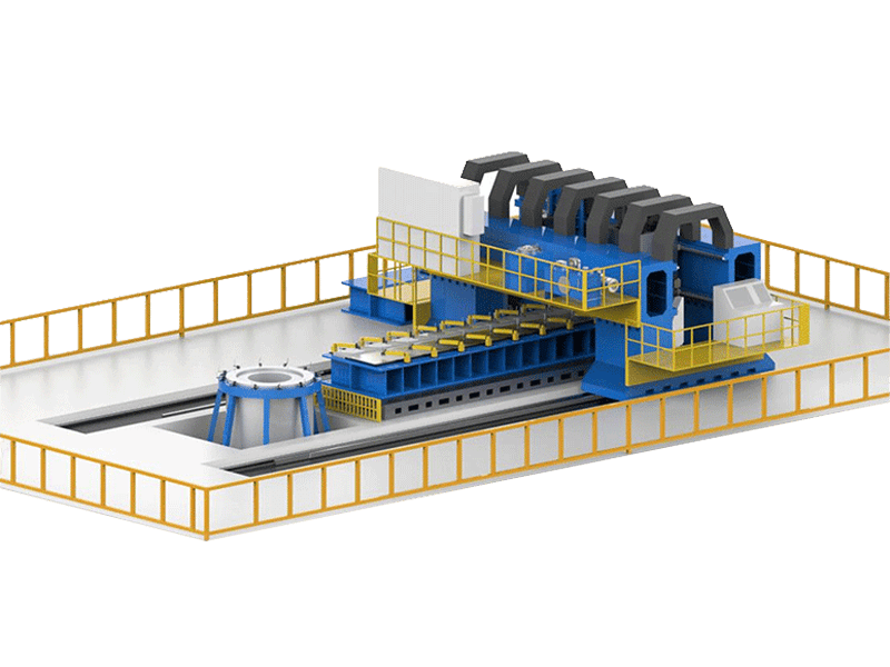
Mixed production creates a genuine compromise. A plant welding 3 mm battery tray lids and 20 mm structural sections on one machine will either accept reduced throughput on the thin parts or reduced capability on the thick ones. Two options resolve it: a second machine sized for the thin work, or a dual-worktable configuration where the two spindles or two stations serve different families. Neither is free, and the cost comparison should include floor space and operator attention, not only the equipment price.
When Higher Rotation Speed Stops Helping
Rotation speed is often treated as a productivity dial. In friction stir welding it is a heat input variable, and past a certain point it works against the weld.
Increasing rpm raises the heat generated at the shoulder interface. Up to a limit this softens the material, improves flow and allows faster travel. Beyond that limit the additional heat produces defects rather than speed: excess flash at the shoulder, surface galling, voids where material has been displaced faster than it can consolidate, and accelerated tool wear.
The optimum speed is therefore tied to the torque available and the thickness being welded. A spindle with generous torque at moderate speed can often out-produce a faster spindle that must be run gently to avoid overheating the tool. This is why maximum rpm is a weak headline specification and torque at the working speed is a strong one.
Thin sheet is where the speed ceiling bites first. Below roughly 2 mm, the heat needed to plasticise the material is small, and the risk is burning through or over-softening the joint rather than failing to stir it. Tool designs that separate the shoulder from the rotating pin reduce heat input by removing the shoulder’s frictional contribution. A retractable tool adds a second benefit for closed contours: the pin withdraws into the shoulder at the end of the weld so the exit hole is filled and no keyhole remains.
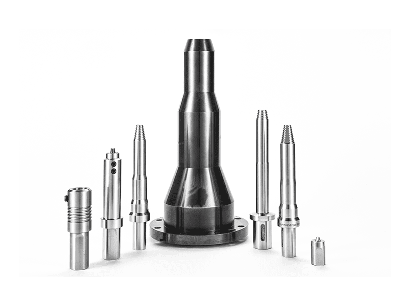
A production line welding sealed enclosures needs this capability designed in from the start. Retrofitting keyhole elimination onto a machine without the retraction axis is not a tooling change, it is a machine change.
Tool Holder, Runout and the Interface Buyers Overlook
The spindle rating is the capability of the drive. The tool holder is what transfers that capability to the tool, and it is the component most often left out of the specification discussion.
Tool holder size follows torque. BT40 interfaces suit the lighter models in the series, BT50 covers the mid to heavy range, and BT60 appears only where the torque is large enough to justify the extra mass. The interface must transmit the full torque continuously without slipping or fretting at the taper, and it must locate the tool concentrically enough that runout stays small. Runout matters because a tool that orbits off-centre produces an uneven weld, asymmetric flash and faster wear on one side of the shoulder.

Mass becomes a factor as tools grow. A heavy tool on a high speed spindle increases the load on the bearings and slows acceleration, which affects cycle time on short welds more than the rated speed suggests. On machines with an angular head, the mounting style changes entirely: flange-mounted spindles such as the SE models in the AEE range are built for 3D heads where a taper interface cannot be accommodated.
Cooling belongs in the same conversation. Standard grease lubrication covers normal duty. Continuous welding of thick sections, or welding copper, raises the heat load on the spindle and the tool, and through-spindle or tool cooling extends both tool life and the achievable duty cycle. Automatic tool change is worth specifying when a line runs more than one product family, because manual changeover between jobs erodes the productivity the larger spindle was bought for.
Spindle options such as automatic tool change, through-spindle cooling and retraction change the machine specification rather than the weld schedule. <AEE provides customer with optional features FSW tool> covers the optional features available on FSW tooling.
Writing Spindle Requirements Into an RFQ
Most spindle specifications fail at the enquiry stage, not at the machine. A request that says “FSW machine for aluminium, 10 mm” gives the supplier nothing to size against and gives the buyer nothing to compare.
Table 3. Fields that determine the spindle answer before price is discussed.
| RFQ field | What to state | Why it changes the spindle answer |
|---|---|---|
| Alloy and temper | Full designation, for example 6061-T6 or 7075-T651 | Flow stress at temperature drives torque demand |
| Thickness and joint | Range plus the dominant production thickness, butt or lap | Sets pin length, shoulder size and force |
| Torque at working speed | The rotation speed you intend to weld at | Rated torque describes only the low speed end |
| Axial force and frame | Required forge force and whether the part needs 1D or 2D motion | Force capacity and structure are specified together |
| Interface and cooling | Tool holder type, tool mass, duty cycle | Determines taper size and cooling provision |
| Acceptance basis | Sample weld, inspection method, documentation | Defines what proves the machine meets the requirement |
The torque line in that table is the one buyers most often miss. Stating a rotation speed and asking for the torque available at that speed converts a vague capability claim into a checkable number. If the intended travel speed is also stated, the supplier can indicate whether the joint is achievable within the envelope or whether a larger frame is required.
An acceptance weld should be specified in the same document. A machine that meets its rated figures on paper still has to produce a joint that passes the inspection method named in the purchase specification, whether that is visual and dimensional, radiographic, or ultrasonic. Naming the method in advance avoids a dispute about what “good weld” means after installation.
The final item is procedure documentation. A spindle sized correctly for the trial but supplied without the parameter records that produced the accepted weld leaves the buyer unable to repeat the result on a second shift. Ask for the welding parameters, the tool drawing and the inspection record as part of the delivery.
Send the Weld Schedule Before You Compare Spindles
Comparing spindle quotations without a weld schedule produces a shortlist ranked by headline rpm, which is the least informative number on the datasheet. Send the alloy and temper, the thickness range and dominant production thickness, the joint type, the weld length and target cycle time, and the inspection method you intend to apply. With those five items, a supplier can state the torque needed at your working speed rather than quoting a peak figure that will never be reached.
Aerospace Engineering Equipment (Suzhou) Co., Ltd. builds spindles and complete FSW machines across the envelope described here, from 1 mm thin sheet to 100 mm aluminium and 35 mm copper, and reviews weld schedules against specific models rather than general capability. Contact [email protected] or +86 18325808715 with your weld schedule and drawings to receive a matched spindle recommendation.
FAQ
Can a spindle deliver rated torque at its maximum speed?
Only when the power rating is large enough to support that combination. For most spindles, the rated torque holds up to a base speed of roughly 1,000 to 1,150 rpm and then falls as speed rises, because the drive holds constant power above that point. The check is arithmetic: multiply power in kW by 9550, divide by the speed in rpm, and compare the result with the rated torque. If the calculated value is lower, power limits the top end of the range.
Which matters more for FSW, torque or power?
Torque determines whether the tool can be turned through the material at the speed the process needs. Power determines how far up the speed range that torque can be sustained. For thick sections and high flow stress alloys, torque is the binding constraint almost every time. For thin sheet where high rotation speed is used, power and speed stability matter more than peak torque.
Do I need a water-cooled spindle for production welding?
It depends on duty cycle and material. Standard grease-lubricated spindles handle normal production on aluminium at moderate thickness. Continuous welding of thick sections, or welding copper where the process runs hot for long periods, raises the thermal load on both spindle and tool, and oil or water cooling of the spindle and tool extends service life. Specify the duty cycle alongside the material so the cooling provision can be sized correctly.
Can one spindle cover both 2 mm sheet and 20 mm plate?
It can cover the thickness range on paper, since series models are listed from 2 mm to 40 mm or beyond, but the compromise shows in productivity. A high torque spindle turns too slowly to make the best use of thin sheet, and a high speed spindle lacks torque for thick plate. Where both families run in volume, two machines or a dual-worktable configuration usually costs less over five years than accepting reduced throughput on one of them.
Does the tool holder type affect which spindle I should choose?
Yes, because the holder must transmit the full torque continuously and keep runout small. BT40 suits lighter spindles, BT50 covers the mid to heavy range, and BT60 appears only where torque justifies the added mass. On machines with an angular head the holder is replaced by a flange mount, so the spindle series must be selected with the head design already decided rather than afterwards.
If you’re interested, check out these related articles:
AEE provides customer with optional features FSW tool
AEE attend 13th International Symposium on FSW in Kyoto, Japan on 21 – 23 May 2024
Refill Friction Stir Spot Welding (RFSSW)