
Force vs. Position Control in FSW Machines: Which Fits?
Table of Contents
- What Force Control and Position Control Change in FSW
- How Force Control Responds to Weld Conditions
- How Position Control Holds Depth and Geometry
- Where Each Control Mode Fits Best
- Comparison Table for FSW Control Modes
- Hybrid Control and Switchable Strategies
- What to Put in Your FSW Machine RFQ
- Acceptance Checks Before You Choose
- Next Step for Your FSW Control Decision
- FAQ
- Is force control always better for thick aluminum?
- Can a position-controlled machine weld variable thickness?
- What force capacity should I specify?
- Do I need both force and position control?
- How do I verify control performance before acceptance?
Force control vs. position control in FSW machines is not a choice between a modern mode and an old one. The two modes regulate different variables. Force control holds axial force and lets Z position move with the workpiece, fixture, and thermal state. Position control holds Z position and lets axial force vary. The right choice depends on thickness variation, joint fit-up, fixture stiffness, tool geometry, and the dimensional tolerance you must hold. Many production machines use both, with one mode for plunge and another for steady-state travel.
What Force Control and Position Control Change in FSW
In friction stir welding, the tool shoulder generates forging pressure while the pin stirs the plasticized material. Axial force, rotation speed, travel speed, and plunge depth interact. The control mode decides which variable the machine holds and which variable is allowed to move.
Force control closes the loop on axial load. A load cell or force sensor measures Z force, and the CNC adjusts the Z axis to keep that force near the setpoint. If the workpiece rises because of thermal expansion, the head moves up. If the fixture settles, the head follows. The result is a more consistent shoulder contact and forging pressure, provided the force setpoint and the machine response are correct.
Position control closes the loop on Z height. The CNC moves the head to a programmed depth and holds it there. Axial force becomes a result of the process, not the controlled variable. If the stack is thicker than expected, force rises. If the stack is thinner or the fixture deflects, force falls. Position control gives direct command over depth, but it does not directly command the load that forms the weld.
Neither mode replaces good joint preparation. Force control cannot close a gap that never closes, and position control cannot hold depth if the backing plate deflects. The control mode manages the machine response to those conditions; it does not remove them.
How Force Control Responds to Weld Conditions
Force control is useful when the axial load must stay inside a window rather than at a fixed height. Long aluminum profiles expand as they heat. A position-controlled head can see the effective stack grow, which raises force and can produce flash, thinning, or excessive shoulder penetration. A force-controlled head moves up instead, keeping the load closer to the setpoint.
The same behavior helps with thickness variation in cast or machined parts. If one section is thicker, force control adjusts Z position rather than letting the shoulder load spike. It also helps when tool wear changes the effective tool length, or when the fixture has some compliance under load. The machine compensates within its force and stroke limits.
Force control has limits. A force setpoint that is too high can push the shoulder too deep, especially on thin sheet or when the backing plate is not flat. A force loop that is too slow can allow force spikes during plunge or at the start of travel. The machine needs enough response speed, force resolution, and stiffness for the part.
The C-type AEE FSW 8×10/2 lists a maximum Z-axis force of 30 kN with a 12 kW, 4000 rpm spindle. That class of machine suits thin to medium aluminum work where force resolution matters more than extreme load capacity. 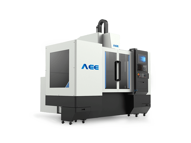
Force control also needs a stable reference. If the part is not clamped, the head may follow a moving workpiece rather than controlling the weld. Clamping force, backing plate support, and fixture stiffness still determine whether the force loop has a stable process to control.
How Position Control Holds Depth and Geometry
Position control is useful when depth and geometry are the dominant requirements. The machine moves to a programmed Z position and holds it. That gives direct control over shoulder penetration, weld crown, and the final surface. On thin sheet, a stable stack, and a stiff fixture, position control can be more repeatable than force control because the depth command does not depend on load-cell drift or force-loop tuning.
Position control also suits closed-contour welds and short seams where the tool starts and ends at defined heights. The operator can set plunge depth, dwell, and retract positions. If the part has a machined pocket or a step, the Z program can follow that geometry. The machine does not need to infer the surface from force.
The tradeoff is that position control does not see thickness variation. If the stack grows, force rises. If the fixture deflects, the actual depth changes even though the Z command does not. A gantry machine may list 0.03 mm positioning accuracy and 50 kN maximum Z force, but those ratings describe the machine, not the welded assembly. The fixture and thermal state still determine the effective depth at the tool.
Position control is not automatically more precise. It controls position, not force. If the process window is force-limited, a position-controlled machine can produce flash or thinning even when the Z axis is accurate. The WPS must state the allowed force range, and the operator must monitor it.
Where Each Control Mode Fits Best
Force control fits when the axial load is the variable most likely to change during the weld. That includes long seams with thermal growth, variable thickness castings, parts with fixture compliance, and thick sections where forging pressure must stay within a window. It also fits when tool wear or build-up changes the effective tool length over a production run.
Position control fits when the stack is stable and depth is the main requirement. That includes thin sheet, shallow penetration, closed-loop welds, and parts with a stiff fixture and a well-supported backing plate. It also fits when the weld crown and surface profile must follow a programmed geometry.
Hybrid control fits when plunge and travel have different needs. A machine may use force control during plunge to find the surface, then switch to position control for travel. Another may use position control for plunge and force control for steady state. The correct sequence depends on the part, the fixture, and the WPS.
The practical answer to “which do you need” is to identify the limiting variable. If the process fails when force drifts, specify force control. If it fails when depth drifts, specify position control. If both can drift, specify a machine that can switch modes and record both traces.
Comparison Table for FSW Control Modes
| Decision factor | Force control | Position control | What to verify |
|---|---|---|---|
| Thickness variation | Adjusts Z to hold load | Holds Z, load varies | Stepped coupon with force and Z traces |
| Fixture and thermal movement | Compensates within stroke and force limits | Actual depth can change | Load trace and fixture deflection check |
| Shoulder contact and flash | Maintains forging pressure | Depth repeatable, force may spike | Crown, flash, and thinning inspection |
| Thin sheet and burn-through | Needs force limit and flat backing | Preferred when stack is stable | Backing plate flatness and clamp force |
| Tool wear and hot hardness | Can compensate within force limit | May need offset adjustment | Tool wear measurement and weld audit |
| Data and acceptance | Force, Z, and torque traces | Z position and force traces | WPS, acceptance record, and trace review |
For thick aluminum or copper, force capacity becomes a design limit. A heavy-load machine lists 200 kN maximum Z force and 100 mm single-side aluminum welding depth, with a 105 kW spindle and 872 Nm torque. Those ratings show why control mode and machine class must be specified together. 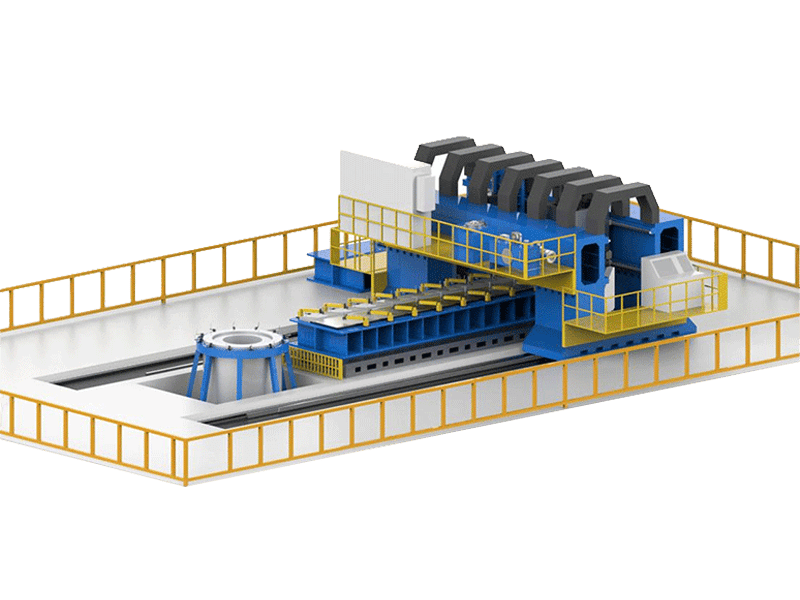
Hybrid Control and Switchable Strategies
Many FSW machines offer force, position, torque, and temperature control. The value of a switchable machine is not that it has more modes. The value is that the WPS can assign each mode to the part of the cycle where it does the most good.
A common strategy is force control during plunge and early travel, then position control for the steady-state pass. Another is position control during plunge, force control during travel, and position control for retract. The correct sequence depends on how the machine finds the surface, how the fixture behaves under load, and how the tool geometry distributes material.
Switch logic must be documented. The WPS should state the force setpoint, the Z position, the switch point, the allowed force band, and the response when the band is exceeded. The machine should log force, Z position, torque, and spindle speed. Without a trace, the operator cannot confirm which mode was active or whether the switch was stable.
Control mode also interacts with spindle and tool design. A machine may hold force well but lack torque at low speed, or hold position well but have insufficient stiffness. The Friction Stir Welding Spindle Series lists torque from 112 Nm to 874 Nm and maximum force from 30 kN to 200 kN across models, so the control loop and spindle envelope must be specified together. 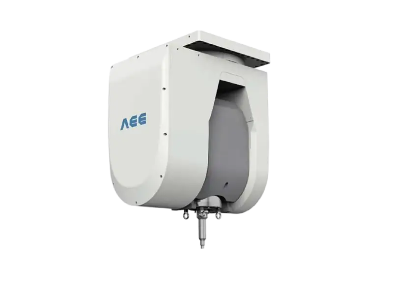
Control mode is only one part of the machine specification, and optional features can change how force and position are monitored. <AEE provides customer with optional features FSW tool> covers how optional tooling and process features are configured for FSW projects.
What to Put in Your FSW Machine RFQ
An RFQ that asks only for “force control” or “position control” leaves the supplier to guess the process window. State the part and the failure mode you need to control.
Include the alloy and temper, thickness range and thickness variation, joint type, weld length, and the required penetration and crown. State the fixture tolerance, backing plate material and flatness, and clamping method. State the force window and the Z position window if both are known. State the cycle time and the number of stations.
Ask for the machine’s rated Z force, spindle torque, spindle speed, positioning accuracy, and repeatability. Ask how the control loop responds to a step change in thickness. Ask for force and position traces from a coupon that represents the thinnest and thickest sections. Ask how tool wear is compensated and how the WPS records the switch logic.
A dual-worktable C-type machine can keep one station loading while the other welds, but the control mode must still suit the part. The AEE FSW 8×10/2S lists 30 kN maximum Z force and 0.05 mm positioning accuracy, with a 15 kW, 6000 rpm spindle. 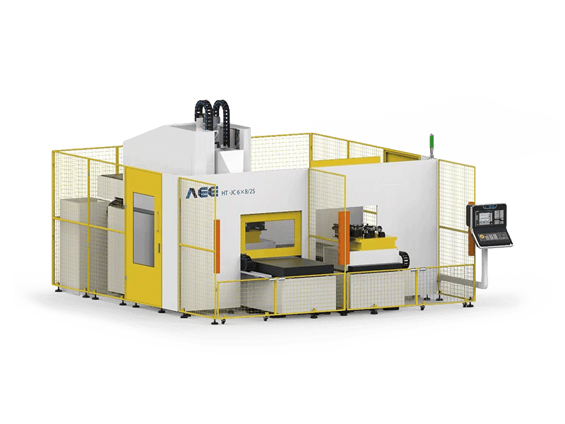
Acceptance Checks Before You Choose
- Weld a coupon that includes the thinnest and thickest sections, the same alloy and temper, and the same joint type as production.
- Log force, Z position, torque, and spindle speed through plunge, travel, and retract.
- Inspect crown, flash, thinning, and penetration at the start, middle, and end of the weld.
- Check fixture deflection under load and confirm that the backing plate stays flat.
- Repeat the coupon after a tool wear interval and compare the traces.
If the force trace drifts upward while Z position falls, the effective stack is changing. If the Z trace moves outside the allowed band while force stays stable, the fixture or thermal growth is moving the part. Either result tells you which variable needs control.
Next Step for Your FSW Control Decision
Send the part drawing, alloy and temper, thickness range, joint type, fixture tolerance, and cycle-time target. The review can then compare force control, position control, and a switchable strategy against the actual process window. Contact Aerospace Engineering Equipment (Suzhou) Co., Ltd at [email protected] or +86 18325808715.
FAQ
Is force control always better for thick aluminum?
No. Thick aluminum often benefits from force control because forging pressure and load capacity matter, but position control can fit when the stack is stable and depth is the main requirement. The machine must also have enough spindle torque and force capacity. Check the WPS, coupon results, and force trace. A 200 kN machine may suit 100 mm aluminum, but the control mode still depends on fit-up, fixture, and tool geometry.
Can a position-controlled machine weld variable thickness?
It can, but the process window narrows. If thickness changes, the Z position may need to be programmed in steps, or the machine may need force control. Verify with a stepped coupon and inspect for flash, thinning, and lack of penetration. Small variation with a stiff fixture may be manageable. Large variation usually calls for force control or a hybrid sequence.
What force capacity should I specify?
Start from the alloy, thickness, joint type, and tool geometry, then add margin for fixture and thermal loads. Use the machine’s rated Z force, not spindle power alone. For reference, the product library lists 30 kN for a C-type 8 mm machine, 50 to 60 kN for gantry models, and 200 kN for a heavy-load 100 mm aluminum machine. Treat these as examples, not a selection rule.
Do I need both force and position control?
Not always. If the part has stable thickness and the main risk is depth, position control may be enough. If thickness, fixture, or thermal movement changes the load, force control is useful. A switchable machine helps when plunge and travel have different requirements. Put the mode, setpoints, and switch logic in the WPS.
How do I verify control performance before acceptance?
Run a coupon that represents the thinnest and thickest sections, log force and Z position, and inspect crown, flash, penetration, and distortion. Check the fixture under load. Repeat after a tool wear interval. If the force trace drifts or the Z trace moves outside the allowed band, adjust the process or the control mode before acceptance.
If you’re interested, check out these related articles:
Refill Friction Stir Spot Welding (RFSSW)
AEE attend 13th International Symposium on FSW in Kyoto, Japan on 21 – 23 May 2024
AEE provides customer with optional features FSW tool