
FSW Machine CNC Systems: Siemens vs Fanuc vs Proprietary
Table of Contents
- What the CNC Actually Controls on an FSW Machine
- Siemens, Fanuc and Proprietary Controllers Compared
- Matching the Control Architecture to Your Joint Geometry
- Force Control and Retraction Beyond Standard CNC Functions
- Data and Traceability From the Controller to Your MES
- What the Controller Choice Costs You After Installation
- What to Put in the RFQ About the Control System
- Send Your Weld Program Before You Specify a Controller
- FAQ
- Is Siemens or Fanuc better for friction stir welding?
- Can a standard CNC run FSW without a proprietary controller?
- Do I need five-axis interpolation for friction stir welding?
- What should a weld data record contain?
- How do I prove keyhole-free welding before I buy?
FSW machine CNC systems are usually compared on brand reputation, yet the controller rarely decides whether a weld qualifies. What decides it is how the machine builder implements the process layer above the CNC: axial force regulation, tool retraction, path generation for the joint geometry, and the data record that proves the procedure was followed. Siemens, Fanuc and proprietary controllers differ mainly in how much of that layer you must build, license or inherit, and in who can service the machine five years from now. Choosing between them is a question about your weld program, your maintenance capability and your traceability obligations, not about which controller wins a general benchmark.
What the CNC Actually Controls on an FSW Machine
An FSW machine carries two control layers that are usually bought as one package. The motion layer interpolates the axes, holds spindle speed, sequences the tool changer and enforces the safety interlocks. The process layer decides how much axial force the tool applies, how deep it plunges, how it tilts, how it withdraws at the end of the seam, and what gets recorded while all of that happens. A CNC owns the first layer completely. It owns the second only to the extent that the builder has integrated a force actuator and a retraction sequence into it.
That split explains a common buying mistake. Controllers get compared the way machine tools get compared, by positioning accuracy and interpolation quality. Those numbers describe the motion layer. On a C-type machine, a positioning accuracy of 0.03 mm on X, Y and Z is a real specification, because it sets how closely the tool follows a programmed seam and how consistently it returns to a start point on the next part. It says nothing about whether the weld will be sound.
The same limit applies to spindle capability. A 12 kW spindle rated at 112 Nm and 4000 rpm covers a different part of the process window than a 105 kW spindle turning at 1000 rpm. Thick aluminium needs torque at low speed. Thin sheet needs rotational speed with modest torque. A controller can only command what the spindle and drive can deliver, so the torque and speed at your operating point belong in the specification before the controller brand does.
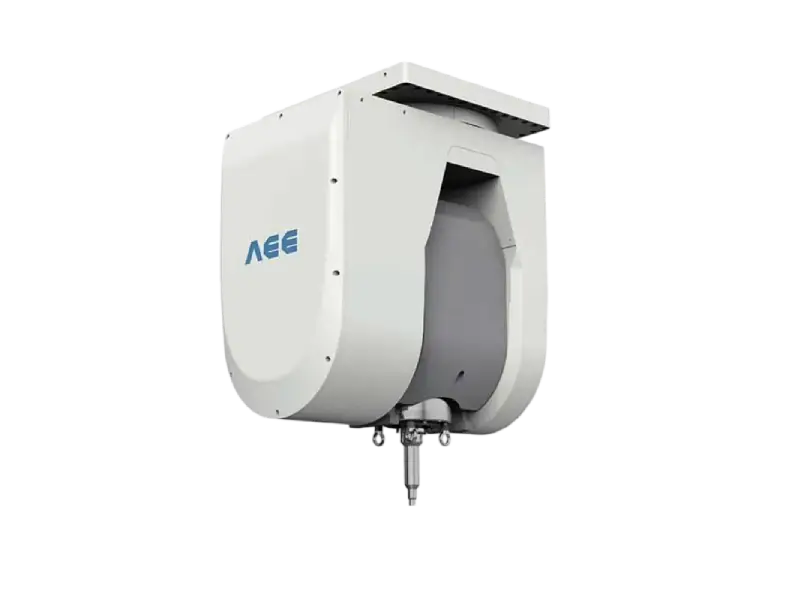
Tool holder interface follows the same order of decisions. BT40, BT50 and BT60 interfaces appear across the spindle range, and each one fixes the shank stiffness and the torque the assembly can transmit. It is a mechanical choice that constrains the control choice, not the other way round.
Siemens, Fanuc and Proprietary Controllers Compared
The three options differ less in what they can compute than in where the process knowledge sits.
A Siemens SINUMERIK system is a general-purpose CNC with an integrated programmable logic controller, a drive family and a documented engineering environment. On the dual-worktable C-type machine, a SINUMERIK 828D handles four-axis linkage across six numerical axes, enough for X, Y, Z and C interpolation with two feed stations. The practical advantages are a large pool of engineers who already know the platform, standard programming tools, and predictable spare part logistics in most industrial regions.
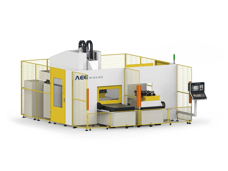
A Fanuc system is also general purpose, and it usually arrives as a matched set of CNC, servo drives, motors and spindle. That matching reduces the integration work for the builder, because control, drives and motors are tuned as one system rather than assembled from separate suppliers. In plants where Fanuc-based equipment already dominates the maintenance department, the familiarity is often worth more than any individual feature difference.
A proprietary controller is built by the machine builder around the welding process. It typically combines a motion controller, a PLC and a custom HMI, with force regulation, withdrawal ramps and weld recipe management written as native functions rather than added afterwards. The trade is straightforward: more of the process arrives ready to use, and more of your machine knowledge sits with one supplier.
| Approach | What it typically delivers | Where it stops | Do not infer |
|---|---|---|---|
| Siemens SINUMERIK | Standard CNC, PLC and drive platform; broad engineering and service base; documented programming environment | Force control and retraction remain builder functions that must be integrated and validated | That a named CNC model alone specifies the welding capability of the machine |
| Fanuc | CNC, drives, motors and spindle tuned as one matched system; strong presence in high-volume plants | The same integration work for force and retraction; parameter access depends on the builder’s release policy | That matched hardware removes the need for a process acceptance test |
| Proprietary builder controller | Process functions native; one HMI for welding, monitoring and recipes | Knowledge, spares and software updates concentrated with one supplier; migration needs a contractual answer | That a proprietary system is automatically better matched to FSW, or automatically harder to maintain |
The table does not say that any of the three is disqualified by the weld itself. In practice each can hold a qualified procedure. The differences appear in engineering hours, in who can service the machine locally, and in how much of the process record you can extract without asking the builder for help.
Matching the Control Architecture to Your Joint Geometry
Controller selection gets easier once the joint is fixed. Kinematics decide which axes the CNC has to interpolate, and seam length decides whether tracking and thermal drift matter as much as interpolation quality. The values below reflect the configurations in a current build range and show the scale of each case rather than setting a requirement.
| Workpiece and joint | Axis and kinematic demand | What the control must handle |
|---|---|---|
| Short straight butt seams on small parts | X, Y, Z with 2D positioning in the 0.03 mm class | Simple interpolation, plunge and dwell sequencing, repeatable start point |
| Long straight profiles for rail or ship panels | X travel in the metres to 16 m range, with laser seam tracking | Following a moving seam reference, compensating thermal growth over distance, holding travel speed |
| Contoured panels with constant weld angle | X, Y, Z plus C rotation of N x 360 degrees | Keeping tool orientation relative to the seam while the path curves |
| Curved 3D structures | A axis around plus or minus 100 degrees, C around plus or minus 360 degrees | Five-axis interpolation, orientation limits, force regulation as the tool normal changes |
| Thick plate up to 100 mm aluminium | Heavy Z force capability in the 200 kN class | Force regulation as the primary loop, with position as a secondary limit |
| Closed contours and circumferential welds | C rotation with a retraction-capable tool | Synchronising pin withdrawal with spindle and feed to close the exit hole |
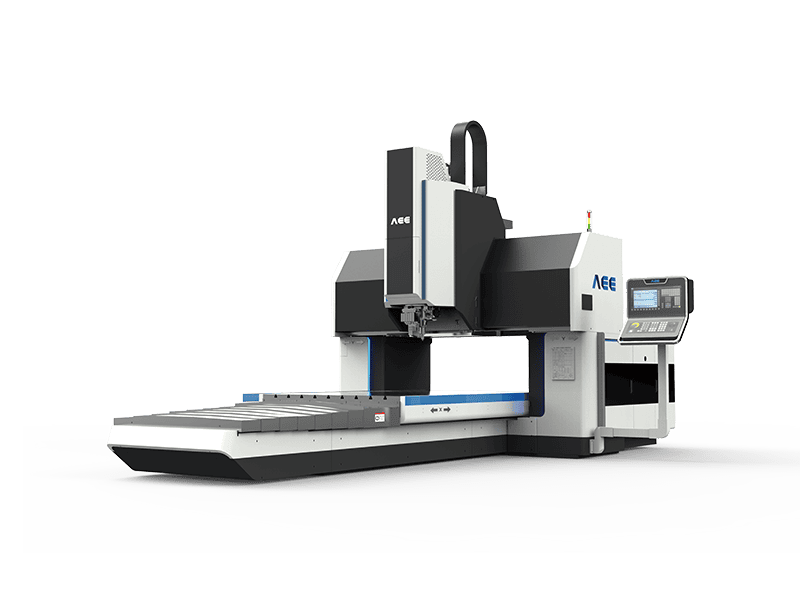
The 3D case is the demanding one. As tool orientation changes, the contact condition at the shoulder changes with it, and the axial force needed to hold the same heat input varies along the seam. A controller with limited look-ahead forces the programmer to slow travel speed at every orientation change to stay inside the process window, which is a productivity loss that no brand comparison will show you. Ask for a demonstration on a representative curved part rather than a flat plate.
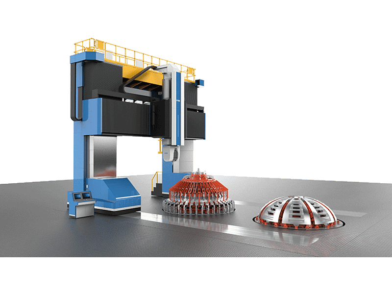
Long straight seams raise a different problem. Over several metres, workpiece and machine frame expand at different rates as the weld heats the part, and a seam aligned at the start is no longer aligned at the end. Seam tracking and a stable, repeatable travel speed matter more here than fine interpolation. This is also where an extra-length machine with automatic start-point setting and parameter acquisition earns its cost, because the operator cannot correct drift by hand at 16 metres.
Force Control and Retraction Beyond Standard CNC Functions
Axial force is the variable that decides weld quality, and it is the one a milling CNC was never designed to regulate.
In friction stir welding the tool does not cut. It stirs a plasticised volume and forges it behind the pin. Axial force sets how much material is displaced and how much frictional heat is generated. Too much force thins the joint and pushes flash past the shoulder boundary. Too little leaves insufficient forging pressure behind the pin, and the result is a void or tunnel that may not appear until the part is machined or pressure tested.
Position control alone struggles to hold that force. As the workpiece heats it expands, as the fixture settles the gap changes, and as the tool wears the contact geometry changes. A machine that only commands Z position will see force drift along the seam. Practical FSW machines therefore regulate force directly, either with a dedicated force axis or with an outer loop that trims the position command from a load cell reading. The heavy load configuration combines force and position control with integrated data acquisition, and it is rated for 200 kN on the Z axis, the scale required for aluminium up to 100 mm.
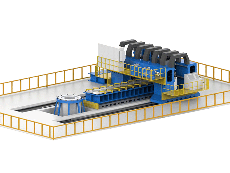
Four questions settle whether that loop is worth its price. Where does the load cell sit, and how often is it calibrated? What does the control do when the reading leaves its valid range? Does the force loop keep running through a brief communication fault? Which party signs off the force calibration after installation?
Retraction is the second function with no equivalent in a standard CNC canned cycle. To close the exit hole, the pin withdraws into the shoulder while the shoulder keeps material confined, and the timing of that withdrawal against spindle speed and feed determines whether the hole fills cleanly or leaves a witness mark. The sequence is short, but it is a coordinated multi-axis move with a force condition attached, and it has to be proven on the alloy and thickness you intend to weld.
A closed contour is only half the problem, because the exit hole still has to be filled without leaving a visible mark. <Refill Friction Stir Spot Welding (RFSSW)> covers refill friction stir spot welding and how the refill cycle closes the keyhole.
Spot welding pushes the same principle further. A friction stir spot welding cycle is closer to a servo press profile than to a milling path: compression sleeve, stir sleeve and stir pin move in a defined sequence within seconds, and the control has to hold force and position for each element in turn. A controller that is excellent at contour interpolation may still need a separate press-style motion module for that work, which is why spot welding specifications should be written around the cycle rather than around the CNC model.
Data and Traceability From the Controller to Your MES
A qualified welding procedure is only defensible if production records show the qualified window was actually used. That makes the data path a specification item, not an IT afterthought.
Decide what has to be recorded per joint: recipe identifier, part or joint identifier, axial force, spindle torque and speed, travel speed, timestamps, operator, tool serial number and tool life count, and the calibration status of the force sensor at the time of welding. Then decide where the record is produced. If the controller writes it, the data usually shares a clock with the machine. If a separate monitoring unit writes it, the two clocks must be synchronised, or the trace will not line up with the machine event that caused a deviation.
Export format matters as much as content. Ask for CSV or JSON output, name the sampling interval, and confirm retention period and who owns the archive. A proprietary binary log that only the builder’s software can open is a dependency you agree to at purchase and renegotiate later at a disadvantage. On the network side, confirm whether PROFINET, EtherNet/IP or an OPC UA gateway is native to the controller or added as a converter, because converters become the first suspect whenever data stops arriving.
Remote support closes the loop. Establish what the builder can see, whether access runs through a VPN you control, and how long session logs are kept.
What the Controller Choice Costs You After Installation
The purchase price of a control platform is the least informative number in the comparison. The costs that accumulate are spares, skills, software and documentation.
Spares come first. Ask which boards and drives are stocked in your region and what the lead time is for a replacement drive. Then ask about the force actuator: a standard servo motor is a catalogue item, while a bespoke hydraulic unit may be a single-source part with a repair cycle measured in weeks.
Skills come second. A plant whose maintenance team already tunes Siemens or Fanuc systems recovers from a fault faster than a plant learning a new platform during a production stop. That advantage is real but local, so evaluate it against your own staff rather than against a general reputation.
Software and documentation come third, and they are where proprietary systems need the most careful negotiation. Licensed axis options, option bits and firmware updates all carry terms. At handover, ask for PLC logic, the HMI project, a parameter archive and a written restore procedure. If the builder will not release source files, negotiate an escrow or a documented recovery service with a stated response time.
Migration is the last item. Standard platforms have long product lives but are eventually discontinued. Ask what the builder’s replacement path looks like and how much recipe and HMI data survives it.
What to Put in the RFQ About the Control System
A control specification that names only a brand invites a machine that meets the brand and not the process. These ten items close most of the gap.
- State the joint family, part drawings and thickness range, because kinematics and force range follow from geometry rather than preference.
- State the required force range and the control method, including load cell location and calibration interval.
- State whether keyhole-free welds are mandatory, and require a retraction demonstration on your alloy and thickness.
- List the data fields, export format, sampling interval and retention period you need.
- Name the plant network protocol and confirm whether it is native or requires a gateway.
- Require PLC logic, HMI project and parameter archives at handover, with a documented restore procedure.
- Specify the tool holder interface and the spindle torque and speed at your operating point.
- Define the acceptance test: which welds, which inspection method, which criteria, and who signs.
- Request a spare parts list with lead times for the controller, drives and force actuator.
- Ask what changes in the control architecture if you later add a second head or a second machine.
One substitution does most of the work. Reject the line “Siemens CNC control” or “Fanuc CNC control” on its own, and replace it with the model, the number of interpolating axes, the force control method and sensor location, the retraction function demonstrated on a named alloy and thickness, the data export path and sampling interval, and the backup documents delivered at handover. A supplier who can answer all six in writing has already shown how the process layer is built.
Send Your Weld Program Before You Specify a Controller
Four items decide most control specifications: the joint drawings, the alloy and thickness range, the cycle time you need, and whether keyhole-free welds are mandatory. Send them to Aerospace Engineering Equipment (Suzhou) Co., Ltd and we will respond with the axis configuration your parts actually require, the force range that applies, whether a standard CNC platform with an integrated force loop covers the job or a retraction-capable function is needed, and an acceptance test outline you can place directly in the purchase order. Email [email protected] or call +86 18325808715 to start the review.
FAQ
Is Siemens or Fanuc better for friction stir welding?
Neither is better in the abstract. Both are general-purpose CNC platforms that handle the motion layer well, and the weld outcome depends on how the builder integrates force control, retraction and monitoring above that layer. Choose on service coverage where the machine will run, on your maintenance team’s existing experience, and on how openly the builder shares PLC logic and data export. Ask each bidder to demonstrate the same joint on the proposed platform, then compare the process records rather than the brochures.
Can a standard CNC run FSW without a proprietary controller?
Yes, provided the builder adds a force regulation loop and a retraction function and validates both on your joint. A standard CNC already handles interpolation, spindle command, tool changing and interlocks. The added work is the force actuator and its interface to the position loop, plus the withdrawal sequence if you need keyhole-free welds. Ask where the force sensor sits, how the loop behaves on a sensor fault, and whether the retraction parameters stay open to your process engineer after handover.
Do I need five-axis interpolation for friction stir welding?
Only when the seam is genuinely three-dimensional. Straight butt seams need three linear axes. Contoured panels are usually handled with X, Y, Z and a C rotation that holds the tool angle constant. Curved structures need an A axis as well so the tool can follow the surface normal. Adding axes you do not need raises cost and programming effort without improving the weld, so map your part family before you specify kinematics.
What should a weld data record contain?
At minimum: recipe identifier, part or joint identifier, axial force, spindle torque and speed, travel speed, timestamps, operator, tool serial number, tool life count, and the calibration status of the force sensor at the time of welding. The record is only useful if it can be exported without the builder’s software, so specify CSV or JSON output and the sampling interval in the purchase order. If a separate monitoring unit writes the log, confirm which clock is authoritative.
How do I prove keyhole-free welding before I buy?
Require a demonstration on your alloy and thickness, with the same tool and retraction hardware you will receive, and inspect the exit region by the method your application demands: visual, penetrant, radiographic or sectioning. Ask which retraction parameters were used and whether your process engineer can adjust them after handover. A flat plate demonstration on a different alloy proves the function exists, not that it works in your joint.
If you’re interested, check out these related articles:
AEE attend 13th International Symposium on FSW in Kyoto, Japan on 21 – 23 May 2024
Refill Friction Stir Spot Welding (RFSSW)