
FSW Automation Roadmap: From Single Machine to Full Line
Table of Contents
- What Changes When One FSW Machine Becomes a Line
- Why the Part Family and Weld Geometry Come Before Equipment
- Which Functions Must Run Without an Operator
- Which Process Gaps Automation Exposes and How to Close Them
- Matching the Throughput Architecture to Your Cycle Time
- Building the Data and Quality Loop Before You Remove People
- Phasing the Investment So You Do Not Buy Twice
- Send the Weld Data Before the Machine Specification
- FAQ
- Can an existing manual FSW machine be upgraded into an automated line?
- How do you eliminate the exit hole on a closed contour?
- Is a double-head machine better than two single-head machines?
- What should be recorded for each weld?
- How long does the transition take?
- References
Moving from one friction stir welding machine to a full FSW production line is a process decision before it is a capital decision. The machine already on the floor proves the weld is possible; a line has to prove the same weld is repeatable without an operator standing at the fixture. Three variables control how far the automation must go: the part family and its weld geometry, the cycle time the business case needs, and how much of the load, clamp, weld and inspect sequence can be made self-checking. This roadmap follows those decisions in the order that keeps a first line from becoming a second purchase.
What Changes When One FSW Machine Becomes a Line
On a standalone machine, the operator is the control system. They judge fit-up by eye, listen to spindle load, feel when a tool has lost its edge, and decide whether the seam looks right before the next part goes on. A line has to replace those judgments with interfaces that do the same work: force control, seam tracking, tool condition management, and a record that ties each weld to its parameters.
The first change is where the time goes. A C-type machine with a 600 mm by 1,200 mm table and a maximum welding speed of 3,500 mm per minute covers a full-length seam in roughly 21 seconds of arc time. Loading, clamping, tool change and unloading usually take minutes rather than seconds. Welding is therefore a small share of the cycle, and buying more welding speed buys little. The seconds that matter sit around the arc.
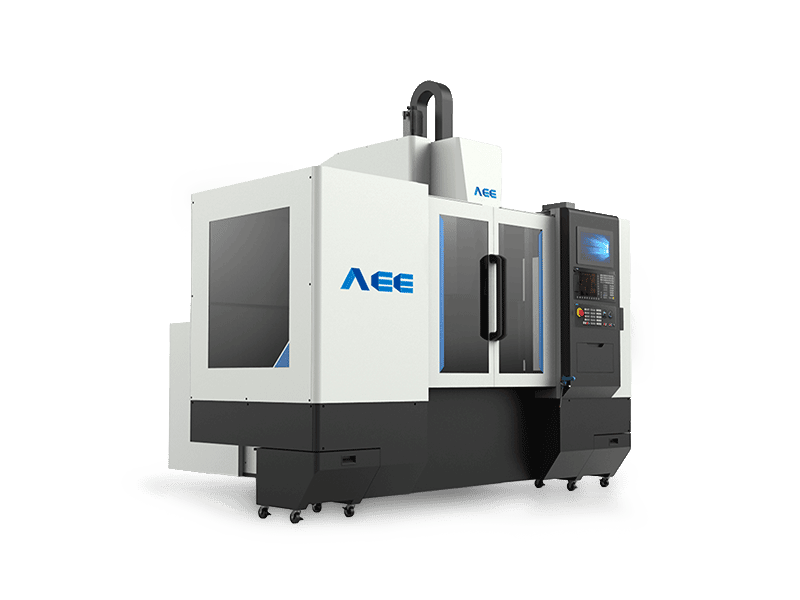
The second change is where variation comes from. A positioning accuracy of 0.03 mm describes the machine, not the joint. Once an operator stops checking fit-up by hand, part-to-part tolerance, fixture wear and thermal growth become the variables that produce defects, and the line needs either a fixture that absorbs them or a sensor that corrects for them.
The third change is that the process has to finish by itself. An exit hole, a backing bar that must be positioned by hand, or a tool that fails without warning all turn into line stoppages instead of inconveniences. A roadmap that does not close those three gaps will end with an automated machine and a manual bottleneck on either side of it.
Why the Part Family and Weld Geometry Come Before Equipment
Thickness sets the spindle and force requirement, the weld path sets the number of controlled axes, and the seam length sets the table and stroke. Quoting equipment before those three are fixed usually produces either an oversized frame or a machine that cannot reach the last 200 mm of a seam.
| Weld geometry and thickness | Axes required | Machine class that fits | Reference capability |
|---|---|---|---|
| Straight butt seams up to 8 mm | X, Y, Z | C-type frame | 8×10/2, 12 kW, 112 Nm, 30 kN |
| Circumferential seams on wheels and housings | X, Y, Z plus C rotation | C-type with C-axis | C-axis N times 360 degrees |
| Curved shells and domed surfaces | A tilt plus C rotation | 3D machine | 12×40/3, A-axis plus or minus 100 degrees |
| Panels 16 to 25 mm thick | X, Y, Z on a gantry frame | Gantry | 25×40/1, 25 mm, 60 kN, 31 kW |
| Profiles longer than 6 m | X stroke beyond table length | Extra-length straight profile | 8×160/1, 16,000 mm X stroke |
| Aluminium 25 to 100 mm single side | Heavy gantry with force control | Heavy-load machine | 100×100/2, 100 mm, 200 kN |
Below about 8 mm in aluminium, a C-type frame with a 12 kW, 112 Nm spindle and 30 kN of Z-axis force covers most structural work, and its compact footprint keeps the cell inside a normal bay. Between 16 and 25 mm the force requirement moves to 50 to 60 kN and the frame becomes a gantry with a table measured in metres. At 100 mm single-sided aluminium in a 120 t machine with 200 kN of Z-axis force, the difference is not price; it is what each frame can hold flat while the pin is buried.
Path complexity is the second filter. A 1D machine welds straight seams in one plane. A 2D machine adds a rotating C-axis so a circumferential seam can close without repositioning the part, which is what makes wheel, motor housing and flange work automatable. A 3D machine adds a tilting A-axis so the head follows a curved surface. If the drawing shows curvature in two directions, a 2D machine will need a repositioning fixture, and a repositioning fixture needs a person.
The third filter is whether the part family is one product or several. A line built around a 17 to 22 inch wheel with 1.2 to 10 mm sections is a different machine from one built around 18.5 m extruded profiles. Where both must run, name one as the design driver and treat the other as a guest with an acceptable changeover.
Material combinations belong in this step as well. When the family includes aluminium to steel or aluminium to copper, the tool and parameter window is usually the first unknown, not the frame.
Where a part family includes aluminium to steel or aluminium to copper, the tool and parameter window usually has to be developed before the frame can be specified. <Customized Dissimilar Material Welding Manufacturers in China> covers customized dissimilar material welding as a production topic.
Which Functions Must Run Without an Operator
The specification question is not which features exist but which features remove a decision that a person currently makes. Sort the list before the quotation stage.
| Function | What it takes away from the operator | Required or optional | Check before you specify it |
|---|---|---|---|
| Force control in Z | Judging penetration by sound and look | Required when thickness varies or parts are not flat | Whether force and position switch per recipe |
| Laser seam tracking | Nudging a mismatched seam into position | Required when fixture tolerance exceeds half the seam width | Tracking range and behaviour on curved seams |
| Automatic tool change | Stopping the line to swap a worn tool | Required when tool life is shorter than a shift | Spindle taper and number of tool positions |
| Constant pressure control | Compensating for thickness variation by hand | Optional, useful on castings and stamped parts | Whether pressure holds through the whole seam |
| Process data logging | Writing parameters down | Required when traceability is a customer requirement | Sampling rate and export format |
| Vision or code identification | Selecting the wrong recipe | Required on mixed-model lines | Read reliability on the actual part surface |
Force control and position control are not competing features. When a part is fixtured flat and thickness is consistent, position control holds the pin at a fixed depth and the process is stable. When thickness varies or the part springs, force control holds the Z load at a set value and lets position follow, at 30 kN on a C-type frame or 200 kN on a heavy-load gantry. The question worth asking is whether the control can switch modes per recipe and record which mode ran.
Automatic tool change earns its cost in two situations: tool life shorter than a shift, and several thicknesses running on one line. A dual-worktable C-type machine pairs tool change with a Siemens SINUMERIK 828D control running four interpolating axes from six numerical axes, which is also the platform on which laser tracking, visual recognition and weld monitoring become practical additions.
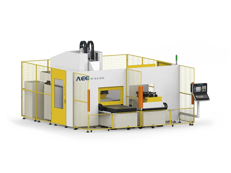
Several of these functions look optional until the operator leaves. Laser tracking is the clearest case: on a manually loaded machine a person absorbs seam mismatch with a nudge, and the same mismatch becomes a defect once nobody is there to absorb it. The tracker moves from convenience to prerequisite at that point, not before.
Which Process Gaps Automation Exposes and How to Close Them
Every FSW process leaves something behind that a person normally handles, and a line removes the person before removing the problem.
The exit hole is the first. A conventional tool withdraws and leaves the end of the seam unfilled. On an open seam this is trimmed away; on a closed contour such as a wheel, a motor housing or a sealed cooling plate there is nowhere to put it. Three tool families answer differently. A retractable tool withdraws the pin into the shoulder while the shoulder stays on the surface, so plasticized material backfills the cavity. A bobbin tool uses a shoulder on each face and removes the need for a rigid backing bar. A stationary shoulder tool rotates only the pin and slides a non-rotating shoulder across the surface, which lowers heat input and leaves no flash and no thinning. The part decides: bobbin tools for hollow profiles and long straight seams, stationary shoulder tools for thin walls and low distortion, retractable tools for closed contours that must finish inside the component.
Backing support is the second. A rigid backing bar is simple on a flat table and awkward inside a fixture that also has to locate, clamp and release. Removing the requirement changes fixture design, load path and floor space at the same time.
Spot joints are the third. Where the line replaces rivets or resistance spot welds, the joint is a spot rather than a seam, and a dedicated spot head changes the machine architecture. Supplier comparisons for robot friction stir spot welding claim shear strength around 30% above resistance spot welding and energy use more than 90% lower. Those are supplier figures, and they belong in a business case only after they are reproduced on your own coupons.
Exit holes and spot joints are separate problems, and a line that needs both usually needs two tool families rather than one compromise. <Refill Friction Stir Spot Welding (RFSSW)> covers refill friction stir spot welding as a spot joining process.
Matching the Throughput Architecture to Your Cycle Time
Throughput architecture follows from one question: what is the part doing while the pin is not welding?
| Configuration | Where the throughput comes from | Limit to check |
|---|---|---|
| Single C-type, one table | Nothing; handling sits inside the cycle | Table size against seam length |
| Dual-worktable C-type | Loading and welding overlap | Two independent programs and interlocks |
| Double-head gantry | Both sides of a symmetric part weld at once | Access to both faces and head synchronisation |
| Long-table gantry | Long seams without repositioning | Table flatness over the full length |
| Extra-length straight profile | 16 m of X travel for rail and marine work | Floor length, foundation and part support |
| Fully automatic double-head line | Handling, welding, cutting and unloading in one sequence | Changeover time between profile families |
If the part is being clamped by hand, a second table removes more cost per part than a faster spindle. If it is waiting for the first side to cool before the second side is welded, a double-head machine removes the wait: 2.5 m per minute travel, up to 6,000 rpm, and 8 mm double-sided. If it is a 16 m rail profile, the machine has to move and the part has to stay still, which means a 16,000 mm X stroke in a frame roughly 20 m long, with EN 15085 qualification for rail body structures.
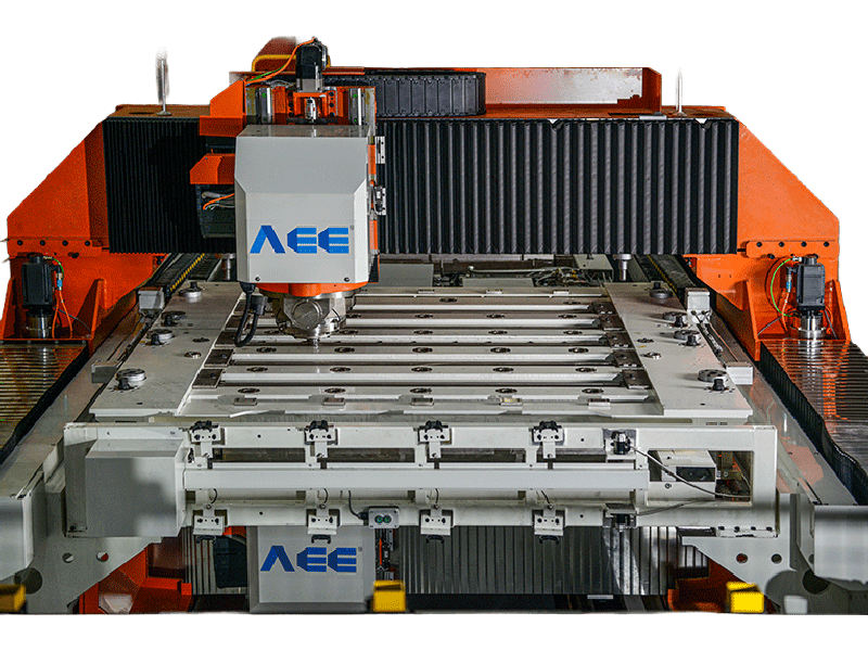
If the part is moving between stations, the problem is handling rather than welding. A fully automatic double-head line welds 1.2 to 16 mm profiles up to 18.5 m long and 3.5 m wide, with water-cooled pin tools, laser tracking and in-line cutting, so the workpiece is loaded once and leaves finished.
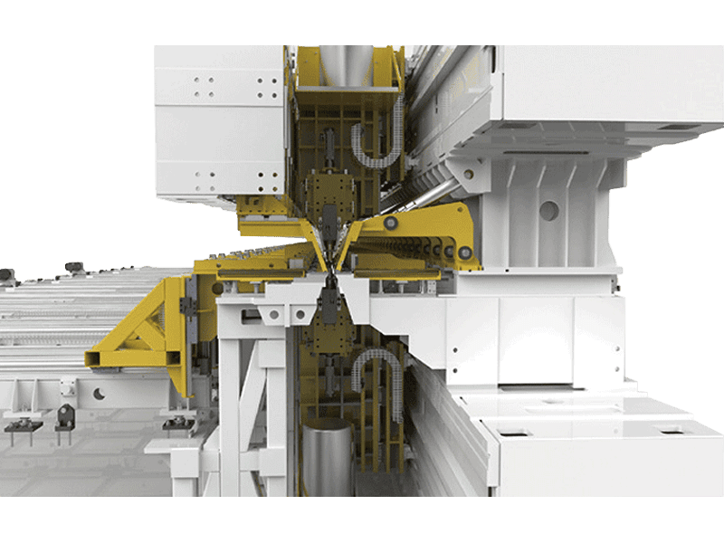
The rule that keeps the capital plan honest is simple: automate in order of seconds recovered per unit of capital, and stop when the next step cannot be justified by a measured cycle time.
Building the Data and Quality Loop Before You Remove People
Removing people from the weld does not remove the need to prove the weld. It moves the proof into records.
A line runs from recipes, and each recipe should map to a qualified welding procedure. ISO 25239-4 sets out how friction stir welding procedures for aluminium are specified and qualified [1], and the qualified window of rotation speed, travel speed, Z force and tilt is what the process database must not exceed without requalification.
Per-weld records of force, torque, spindle speed, travel speed and, where measured, temperature are what turn a parameter display into traceability, provided they carry a part serial. They are worth building only if a decision depends on them: a Z-force drift across a shift, a torque signature that changes as a tool wears, a temperature change when the backing bar loses contact. Decide which of those you will act on before specifying a sampling rate.
Inspection closes the loop. ISO 25239-5 covers quality and inspection requirements for aluminium friction stir welds [2]. Volumetric defects are detectable with established non-destructive methods; a lap joint’s hooking is a geometric feature that non-destructive testing sizes only with difficulty, so periodic destructive checks remain part of the plan wherever lap configurations run.
Tool management is where data meets maintenance. Tool life should be counted in metres welded and held to a change interval, with the automatic tool change as the record keeper. A tool that ran past its interval and still produced acceptable welds is evidence that the interval can be reviewed, not evidence that it can be ignored.
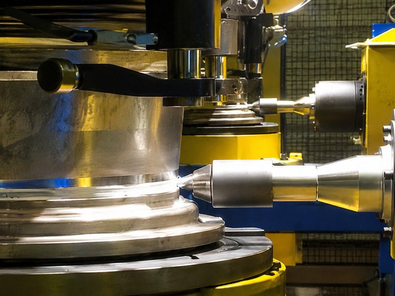
A turnkey wheel line for a European customer shows the loop in its finished form: 17 to 22 inch wheels, 1.2 to 10 mm sections, 45 jobs per hour, a retractable tool that leaves no keyhole, code reading at load, and a welding quality judgment written back to the part record. AEE delivered that line as a complete project rather than a machine with robots attached.
Phasing the Investment So You Do Not Buy Twice
The common mistake is to buy the last stage first. A line purchased before the fixture, the tool interval and the parameter window are understood tends to run at the speed of its weakest manual step, with automation added on top of it.
| Stage | Evidence to collect before advancing | Decision it unlocks |
|---|---|---|
| One machine, manual load | Qualified procedure, tool life in metres, cycle split into weld and handling | Whether handling or welding dominates |
| Second table or second station | Repeatability across a full shift without fit-up adjustment | Whether fixtures or sensors must improve first |
| Automated handling and transfer | Parameter records that predict defects, proven tool change interval | Whether the operator moves from welding to monitoring |
| Full line with in-line inspection and cutting | Changeover time and first pass yield across mixed families | Whether the line can run unattended |
The sequence that avoids the double purchase starts at stage one, where interfaces cost little and cost a great deal later: robot handshake I/O, a safety circuit that accepts an external stop, a data output a line controller can read, and a spindle interface the tooling can follow. On the spindle side, BT40 covers the 12 kW class and one 25 kW model, BT50 covers 25 to 58 kW, and BT60 appears at 105 kW.
Utilities and floor belong in the first layout drawing. Compressed air at 0.6 MPa and about 1 m³ per minute through a φ8 connection is common across the range, with the largest gantry models asking for 0.8 MPa. The machines that change the building are the large ones: a 16 m straight profile machine occupies roughly 20 m by 7 m and weighs 75 t, and a 100 mm heavy-load gantry weighs 120 t. Foundation design, crane access and part support are cheaper to fix on paper.
Then buy seconds. A second table removes handling from the weld cycle for a fraction of the cost of a robot cell, and it proves the fixture before the handling is automated. Automate transfer once the fixture and tool interval are stable, not before.
Write the request in the language of the line rather than the language of the catalogue: part family, alloy and temper, thickness range, weld geometry, seam length, required cycle time, inspection criteria and interface expectations. A request that names only a machine class leaves the supplier to guess which of those the project actually depends on.
Send the Weld Data Before the Machine Specification
A line layout can be proposed once the inputs that set it are on the table: alloy and temper, thickness range, weld geometry in 1D, 2D or 3D, seam length and whether contours close, target cycle time or jobs per hour, fixture concept, tool life expectation, inspection criteria, and available floor space, power and compressed air. Send those together with a drawing of the part as it is welded, not only as it is machined, and the reply can address the sequence rather than a single machine. Contact Dr. Wang Wei at AEE, [email protected], +86 18325808715.
FAQ
Can an existing manual FSW machine be upgraded into an automated line?
Partly, and the answer depends on the control rather than the frame. A machine can accept robot loading if it has an external cycle start, a safety circuit that accepts an external stop, and a fixture datum that repeats. It can join a line data system only if the control exposes force, torque and position at a usable rate. Retrofit cost rises sharply when the spindle has no tool change interface or the control cannot store per-recipe force limits. Check those four points before assuming a retrofit; a second table is often cheaper than making an old machine line-ready.
How do you eliminate the exit hole on a closed contour?
Three tool families solve it differently. A retractable tool withdraws the pin into the shoulder while the shoulder stays on the surface, and plasticized material backfills the cavity. A bobbin tool uses a shoulder on both faces and needs no rigid backing bar, which suits hollow profiles and long straight seams. A stationary shoulder tool rotates only the pin, lowering heat input and leaving no flash or thinning. The choice follows access to the back face and the distortion limit of the part, not preference.
Is a double-head machine better than two single-head machines?
It depends on symmetry and volume. A double-head machine welds both sides of a symmetric part at once and removes the cooling wait between passes, which suits a dominant part family with accessible faces. Two single machines give independent scheduling and redundancy, so one can run while the other is maintained, which suits a mixed family where a stoppage would idle the plant. Choose double-head for volume on one geometry, two machines for variety and uptime.
What should be recorded for each weld?
Part serial and recipe ID, spindle speed, travel speed, Z force, torque, temperature where measured, tool ID with metres welded on that tool, station or operator ID, and the inspection result. The record becomes traceability only when the qualified procedure range is attached to it, so a reviewer can see whether the weld ran inside the window. Sampling rate should follow what you will act on; a faster log that nobody reads is storage, not control.
How long does the transition take?
There is no standard duration, because the schedule is set by procedure qualification, fixture prove-out, operator training and the number of existing parts that must be requalified rather than by machine build. The machine is usually the shortest item on the list, and the qualification sequence is the one that decides when the first production part ships. Plan the stages so that each one can be qualified and signed off before the next is ordered.
References
[1] ISO 25239-4:2020, “Friction stir welding — Aluminium — Part 4: Specification and qualification of welding procedures,” ISO, 2020.
[2] ISO 25239-5:2020, “Friction stir welding — Aluminium — Part 5: Quality and inspection requirements,” ISO, 2020.
If you’re interested, check out these related articles:
AEE attend 13th International Symposium on FSW in Kyoto, Japan on 21 – 23 May 2024
Refill Friction Stir Spot Welding (RFSSW)