
Optimizing 6xxx Aluminum FSW Parameters: Speed, Force, Tilt
Table of Contents
- Why Do 6xxx Aluminum FSW Parameters Need a Different Starting Window?
- What Rotation Speed, Travel Speed, Axial Force, and Tilt Should You Use?
- Why Spindle Torque Is the Practical Limit
- How Axial Force and Tool Tilt Fit the Window
- Which Defects Reveal a Wrong Parameter Window and How Do You Validate It Before Production?
- Reading Defects Back to Their Inputs
- Validation Sequence Before Full Production
- What Should You Do After the Coupon Passes?
- What Questions Do We Hear Most Before Parameter Sign-Off?
- Does 6061-T6 require different FSW parameters than 6063-T5?
- Is higher rotation speed always better for surface finish?
- Should we use force control or position control?
- Why do two identical parameter sets sometimes produce different 6xxx welds?
- What is the fastest way to qualify a 6xxx FSW process without wasting material?
Optimizing FSW parameters for 6xxx aluminum starts with travel speed and axial force, not with rotation speed. In our process development work on battery trays, water cooling plates, and extruded profiles, welds fail more often from insufficient forging pressure or a heat input window that is too wide than from a missing spindle speed. 6061, 6082, 6005A, and 6063 respond predictably when the machine holds force and position consistently. The sequence below moves from first weld coupons to a procedure ready for production without burning through tooling or leaving tunnel defects.
Why Do 6xxx Aluminum FSW Parameters Need a Different Starting Window?
6xxx alloys are age hardenable. Most of their strength comes from fine Mg2Si precipitates that coarsen or dissolve when the weld thermal cycle spends too long above roughly 250 degrees Celsius. That changes the parameter logic. With 5xxx work hardening alloys, the first concern is usually enough heat input to avoid cold lap. With 6xxx T6 material, the first concern is excess heat input in the heat affected zone. A weld can look clean on the surface and still lose 30 to 40 percent of the base metal tensile strength through that zone.
Because of this, we do not begin parameter development by raising rotation speed until the weld face looks shiny. We begin by setting a fast enough travel speed and a high enough axial force to limit the time the heat affected zone spends at the overaging temperature. Then we adjust rotation speed only enough to keep the root sound and the shoulder contact stable. That order matters. It prevents a good looking weld that tears in the wrong location during tensile testing.
The first documented check in our lab is weld pitch, which is travel speed divided by rotation speed in millimeters per revolution. For 6xxx extrusions, a pitch of 0.4 to 0.8 mm per revolution is a practical starting range. Lower pitch raises heat input and widens the heat affected zone. Higher pitch reduces heat input but demands more spindle torque and can leave a root flaw if the pin does not backfill the trailing side. We use weld pitch rather than rpm alone because the alloy responds to material movement per revolution, not just spindle speed.
What Rotation Speed, Travel Speed, Axial Force, and Tilt Should You Use?
The table below is a starting point we use for flat butt welds with a conventional right hand threaded pin and a shoulder diameter about three times plate thickness. It is not a substitute for coupon testing, but it brackets the range where we expect a usable weld before tooling corrections.

| Alloy condition | Plate thickness | Rotation speed | Travel speed | Primary risk |
|---|---|---|---|---|
| 6063-T5/T6 | 2 to 4 mm | 1200 to 1600 rpm | 900 to 1400 mm/min | edge flash and thinning |
| 6061-T6 | 3 to 6 mm | 800 to 1200 rpm | 500 to 900 mm/min | HAZ softening |
| 6082-T6 | 4 to 8 mm | 600 to 900 rpm | 300 to 600 mm/min | root tunnel |
| 6005A-T6 | 3 to 6 mm | 900 to 1300 rpm | 600 to 1000 mm/min | joint line remnants |
| 6061-T4 | 2 to 5 mm | 1000 to 1500 rpm | 800 to 1200 mm/min | lack of fill during plunge |
These windows assume a stiff backing bar and a clamping pitch close enough to keep the sheets from lifting. On our gantry machines, linear speed can reach 5000 mm per minute for thin 6xxx profiles, but a production weld rarely uses that full capability unless the fixture removes heat quickly. The limiting factor is not machine speed. It is whether the trailing edge of the weld remains forged before the material cools below the flow stress window.
Why Spindle Torque Is the Practical Limit
Spindle torque is a better real time signal than rotation speed during 6xxx welding. When travel speed increases at a fixed rotation speed, torque rises because the pin pushes against colder material. If the spindle is already near its torque limit, the weld will either slow down or the controller will drop rpm. On our C type machine, 112 Nm at 4000 rpm is comfortable for 6 mm 6061, but for 8 mm 6082 the same spindle may require a lower travel speed or a smaller pin. Matching travel speed to available torque prevents a weld that starts well and then fades in the middle of a long seam.
How Axial Force and Tool Tilt Fit the Window
Axial force is the variable that turns rotation speed into a real weld. For 6xxx sheet, we start with a shoulder plunge of 0.05 to 0.15 mm into the plate surface and a tool tilt of 1.0 to 2.0 degrees, then let the machine report the resulting Z force. On a rigid C type machine with a 30 kN Z axis, most 6061 and 6063 panels from 3 to 6 mm settle between 6 and 14 kN. That leaves margin for profile flatness variation and tool shoulder wear.
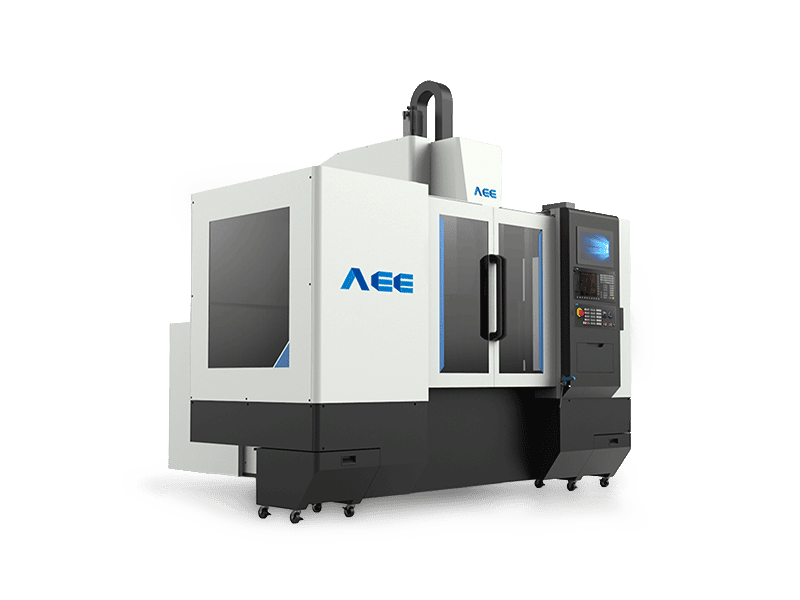
Tilt below 1 degree can produce a poor weld face but less flash. Tilt above 3 degrees pushes too much material to the retreating side and creates a visible flash curl. The practical fix is not always more force. It is usually a flatter profile, a better clamped fixture, or a shoulder design with a small scroll. We use force control for development and position control for production, but force control matters most when the profile thickness varies by more than 0.3 mm along the weld.
If your program includes 6082-T6 sections thicker than 5 mm or a sealed enclosure with leak test limits, it is worth confirming the force and travel speed window on the specific machine model before the BOM is frozen. Send the cross section drawing and weld length to [email protected] and we can map the parameter window against spindle torque, Z force, and fixture capacity.
Which Defects Reveal a Wrong Parameter Window and How Do You Validate It Before Production?
Reading Defects Back to Their Inputs
Tunnel defects in 6xxx welds usually start at the root on the advancing side. They form when plasticized material cannot flow to the trailing side and backfill behind the pin. The common causes are travel speed too high for the available heat, axial force too low to maintain forging pressure, or a pin length too short for the workpiece. Flash is the opposite failure in some ways. It forms when too much material is displaced outward at the shoulder, usually from excessive rotation speed, excessive tilt, or a shoulder plunge deeper than the extrusion surface can absorb. Lack of fill at the start or end of the weld often comes from a plunge sequence or a force ramp that is too slow, leaving a shallow depression before the shoulder reaches full contact.
Tool geometry decides whether the generated heat enters the weld correctly, so parameter adjustments alone cannot rescue a tool with the wrong pin length or shoulder profile. <AEE provides customer with optional features FSW tool> covers optional features that change material flow and shoulder contact, which is why we confirm pin geometry before running a full parameter matrix.
One failure mode we record in coupon trials is a cold root with an acceptable surface. The macro section shows a dark line at the root and the bend test opens it. If the travel speed is raised 20 percent and the root line disappears, the original window was too cold. If the root line remains and torque rises sharply, the pin length or the backing bar is wrong. The parameter answer is not always more rotation.
Validation Sequence Before Full Production
Validation is where most parameter optimization work fails. A bench coupon can pass while a production profile fails because the fixture path, heat sink, and clamping distance are different. We use five checks before signing off a window.
- Weld on the production fixture, not on a laboratory clamping plate.
- Record spindle torque and Z force for the full weld length.
- Section the weld at the start, middle, and end.
- Run tensile and bend tests from the same coupon.
- Repeat the run after the fixture reaches steady state temperature.
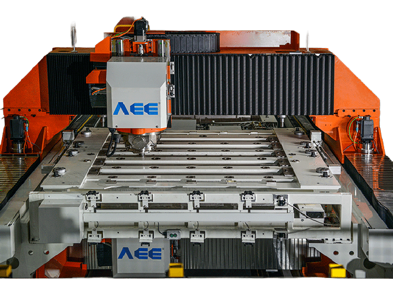
If the window holds after the fifth check, it is ready for a production trial. If not, we adjust travel speed first, then axial force, then rotation speed. That order keeps the thermal profile stable while solving most 6xxx root defects.
What Should You Do After the Coupon Passes?
A passing coupon does not mean the production cell is stable. Clamping stiffness, anodizing thickness variation, profile flatness, and spindle thermal drift all shift the heat input window during a shift. We have seen a weld that ran 1150 mm per minute in the morning drop below 900 mm per minute after two hours because the fixture absorbed heat. If your program moves from feasibility to volume, send your part number, finished thickness, weld length, and target cycle time to [email protected]. We can confirm the machine model and backing bar strategy, then schedule sample welding before you commit to tooling or line layout. Call +86 18325808715 for a direct technical review.
What Questions Do We Hear Most Before Parameter Sign-Off?
Does 6061-T6 require different FSW parameters than 6063-T5?
Yes, but the differences are smaller than most buyers expect. Both alloys weld in a similar heat input window, yet 6061-T6 needs more attention to heat affected zone softening because its T6 strength depends on fine precipitates. 6063-T5 is more forgiving on tensile loss but tends to flash at the shoulder if travel speed is too low. We usually start 6063 at a slightly higher travel speed and accept a higher surface temperature, while 6061 gets a lower rotation speed and a shorter dwell time at the overaging temperature. The fixture, not the alloy label, often drives the bigger difference.
Is higher rotation speed always better for surface finish?
A common misconception is that a shiny, smooth weld face means the highest safe rotation speed. In 6xxx alloys, excessive rotation speed creates a wide flash curl and deepens heat affected zone loss, even when the surface looks bright. The better practice is to hold travel speed and axial force first, then increase rotation only until the shoulder contact ring is continuous. If the surface still shows roughness at that point, the tool shoulder profile or tilt is the usual problem. We have corrected rough weld faces on 6061 by reducing tilt from 2.5 to 1.5 degrees without touching rpm.
Should we use force control or position control?
It depends on the profile tolerance and the production environment. Position control works when plate thickness is stable within about 0.2 mm and the backing bar is rigid. Force control becomes the better choice when extrusions vary in thickness, when anodizing adds uneven surface coating, or when the weld length exceeds several meters. On our C type machines, development runs often use force control to map the acceptable plunge range, then production moves to a fixed position window with force monitoring active. We switch only after the force envelope stays repeatable across five coupons.
Why do two identical parameter sets sometimes produce different 6xxx welds?
In programs we have run, two identical parameter sets rarely mean identical boundary conditions. The difference usually comes from clamping distance, backing bar temperature, tool shoulder wear, or an extruded profile that sits a few tenths of a millimeter higher because of die wear. One set of parameters is not enough documentation. We record torque, Z force, and spindle speed from every coupon and include the fixture temperature at the start of the weld. When a repeatability problem appears, the logged signals show whether the heat input changed or the part condition changed before we adjust the recipe.
What is the fastest way to qualify a 6xxx FSW process without wasting material?
The better question is which parameter window survives production variation, not which single setting passes one tensile coupon. We reduce coupon waste by running a screening design across three travel speeds and two force levels, then sectioning the start, middle, and end of each weld. The final qualification weld uses the production fixture and the same clamping distance as the line. This catches root defects and profile tolerance issues before full tensile work begins. Share your profile drawing and weld length, and we can confirm which machine and tool configuration fits before you spend on coupons.
If you’re interested, check out these related articles:
Refill Friction Stir Spot Welding (RFSSW)
AEE attend 13th International Symposium on FSW in Kyoto, Japan on 21 – 23 May 2024