
Magnesium Alloy FSW: Controls for Automotive and Aerospace
Table of Contents
- What Makes Magnesium Alloy FSW Different from Aluminum FSW?
- Which Magnesium Alloy Grades and Joint Designs Weld Reliably?
- How Do Tool Shoulder and Pin Geometry Affect Magnesium Alloy FSW?
- What Machine Force Control and Fixture Rigidity Does Magnesium Alloy FSW Need?
- What Should Buyers Confirm Before Qualifying Magnesium Alloy FSW?
- What Questions Do Manufacturers Ask About Magnesium Alloy FSW?
- Is magnesium alloy FSW safe in a normal production cell?
- Can high-pressure die cast magnesium parts be friction stir welded?
- Does magnesium alloy FSW require a special machine spindle?
- Which magnesium alloy FSW parameter should be fixed first?
Magnesium alloy FSW joins automotive and aerospace components without melting the base metal, avoiding the hot cracking, porosity, and oxide contamination that complicate fusion welding of AZ31, AZ91, and WE43. The process is not a direct substitution for aluminum FSW. Magnesium moves heat differently, softens across a narrower hot working range, and punishes small errors in shoulder engagement, clamping, or tool position with surface galling, root lack of fill, or failed bend coupons. I treat magnesium as a process control problem first and a machine selection problem second. If the heat input, tool geometry, and backing support are not matched to the alloy grade and joint design, the qualification panel usually fails before the production order starts.
What Makes Magnesium Alloy FSW Different from Aluminum FSW?
Magnesium alloys have a lower melting range than most aluminum alloys, but the more important difference for FSW is how quickly the material loses hot strength near the shoulder. The plasticized band under the tool shoulder is shallower, and the surrounding material offers less backing stiffness because magnesium has a lower hot working strength than 6xxx aluminum. A parameter set that produces a smooth weld in 6061 may tear the edge of AZ31B at the same spindle speed and travel speed.
Heat input control in magnesium alloy FSW starts with the relationship between rotational speed, travel speed, and shoulder diameter. Increasing rotation without increasing travel speed overheats the surface and widens the softened zone, while increasing travel speed without enough plunge force leaves an unwelded root or intermittent tunnel defect. In the magnesium FSW qualification panels I have reviewed, a lower rotational speed and higher axial force setting produced a tighter root and less edge tearing than a faster, lighter pass. The tradeoff is that the machine spindle needs available torque and the fixture needs enough clamp pressure to keep the plates from lifting.
Fire safety is a separate concern for magnesium swarf and fine chips. FSW does not melt the joint, but machining, trimming, and adhesive removal around the weld can create fine particles. Production cells for magnesium should separate chip collection, avoid water-based coolant exposure on hot chips, and store waste in covered steel containers. This is not usually the first issue reviewed in a machine quotation, but it matters for an automotive or aerospace line that will process magnesium parts daily.
Which Magnesium Alloy Grades and Joint Designs Weld Reliably?
Cast and wrought magnesium grades do not behave alike under the same tool. Wrought AZ31B tends to weld more smoothly than high-aluminum AZ91D because the second-phase network in AZ91D localizes deformation and can leave a less uniform nugget flow path. WE43 and ZK60 are more attractive for aerospace and performance automotive parts, but their narrower hot working window and higher deformation resistance usually require smaller shoulder engagement and a more conservative process window.
| Magnesium grade | Form | FSW suitability | Typical joining concern |
|---|---|---|---|
| AZ31B | Wrought sheet/extrusion | Good | Edge tearing and root thinning if travel speed is too high |
| AM50/AM60 | Cast, controlled porosity | Fair | Prior porosity and surface cleaning before welding |
| AZ91D | Cast or thixomolded | Fair to limited | Aluminum-rich second phases and nugget nonuniformity |
| WE43 | Wrought aerospace | Good with tight heat control | Higher deformation resistance and shoulder galling |
| ZK60 | Wrought high strength | Moderate | Narrow process window and hot cracking risk in some tempers |
For butt joints, edge preparation matters less than in fusion welding, but the faces must be clean and clamped with no gap. Magnesium oxide is tenacious, so a wire brush or chemical cleaning step before welding improves surface appearance and reduces oxide entrapment at the shoulder contact line. For lap joints, the hooking defect at the sheet interface is the main failure mode. I review the advancing side and retreating side interface at macro sections instead of relying only on a surface visual check.
Not every magnesium assembly is welded to magnesium. <Customized Dissimilar Material Welding Manufacturers in China> covers how material combinations can be reviewed at the manufacturing stage, which matters when a magnesium housing joins an aluminum bracket or an end plate.
T-joints and corner joints in magnesium need a backing bar with better thermal contact than in aluminum because the material cools quickly and can consolidate only where the backing holds local pressure. A slotted backing plate with a temperature-controlled path is worth evaluating when the part design creates a heat sink on one side of the joint.
How Do Tool Shoulder and Pin Geometry Affect Magnesium Alloy FSW?
Tool geometry sets the practical weld window more than any other single variable in magnesium alloy FSW. A flat or minimally concave shoulder with a scroll pattern lowers surface heat input and reduces flash, which gives a more stable surface for AZ31B sheet and thin castings. The pin diameter should be about 0.9 to 1.0 times the sheet thickness for most butt welds, and the pin root should blend into the shoulder with enough radius to avoid a notch in the softened material.
For magnesium, I avoid the same aggressive shoulder tilt used on thick aluminum. Too much tilt concentrates the trailing edge pressure and tears the surface. A neutral shoulder or small tilt angle plus a tapered pin with threads carries material downward and keeps the root filled without overheating the crown.
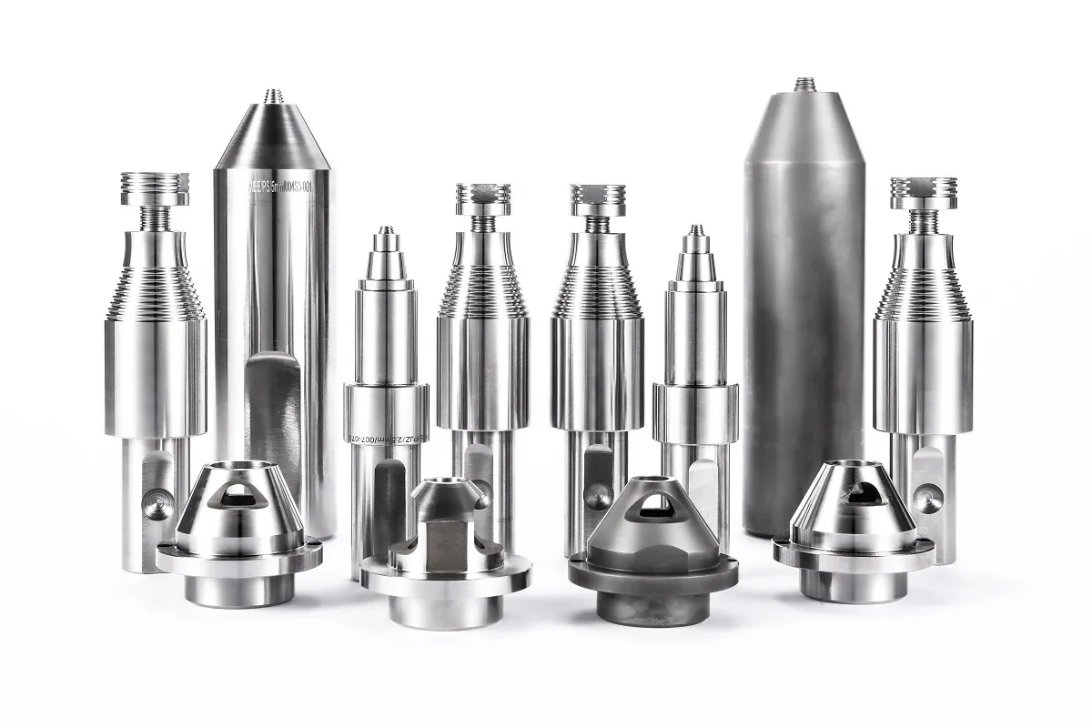
Tool geometry in magnesium alloy FSW should not be left to a default tool set. <AEE provides customer with optional features FSW tool> covers how optional FSW tool features are matched to part geometry and process requirements before hardware is locked.
Retractable pin tools matter for closed contour welds on battery covers, coolant housings, or gear covers because a conventional pin leaves an exit hole. With magnesium, the exit hole is not only a cosmetic issue. It can become a corrosion start point if the component is exposed to road spray or humid service. A retractable pin fills the exit path by withdrawing the pin while the shoulder remains in contact with the consolidated material.
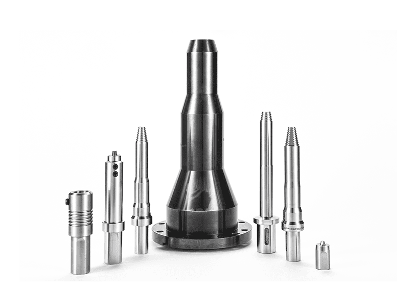
For tool material, PCBN or tungsten carbide may be required for high-volume magnesium production because magnesium can gall steel tools more quickly than aluminum under sustained contact. Polished tool surfaces and periodic inspection of the shoulder contact band catch early wear before the surface finish drifts.
What Machine Force Control and Fixture Rigidity Does Magnesium Alloy FSW Need?
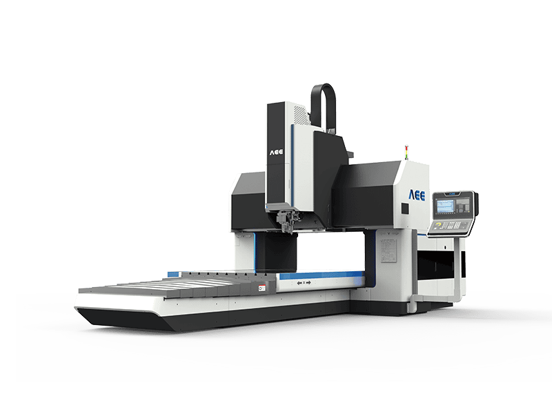
Magnesium alloy FSW does not automatically demand the largest machine in the plant. It demands a machine that can hold axial force steadily while the spindle torque stays within its rated range. A servo-controlled Z axis with force feedback is more important than high traverse speed for most automotive covers, seat frames, and small aerospace housings. The C-type machine is usually sufficient for flat parts up to 8 mm, while a gantry machine is better when the part is longer than the C-type table or needs a 1D to 2D weld path.
The AEE machine and spindle range includes three practical classes for magnesium work, but the selection should follow the axial force and table size needed for the part, not a generic machine size.
| Machine or spindle class | Rated max Z force | Max spindle speed | Practical magnesium range |
|---|---|---|---|
| C-type FSW 8×10/2 | 30 kN | 4000 rpm | Flat parts to 8 mm, research and small production lots |
| Gantry FSW 16×8/1 | 50 kN | 2500 rpm | Medium panels and moderate production |
| S112 spindle | 50 kN | 2500 rpm | Spindle integration for 2 to 16 mm sections |
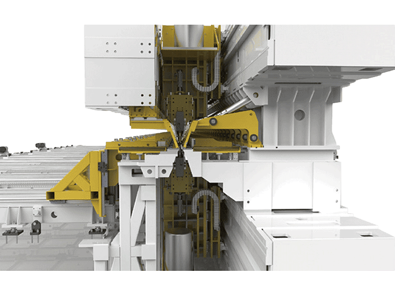
Fixture design needs more contact area and closer clamp spacing than aluminum work. Magnesium loses heat quickly, so a cold section of fixture near the joint can pull heat away and create a root defect that looks like low forge force. Backing bars under the joint should be steel or a heat-conductive material with predictable contact pressure, not a narrow support that lets the sheet spring away from the tool.
If your part is below 2 mm, includes a closed contour, or must pass leak testing after welding, the fixture and retractable pin decision should be settled before machine specification. Send your part material, section thickness, and monthly volume to [email protected] or call +86 18325808715 and we can confirm the force, table size, and backing strategy for your application.
What Should Buyers Confirm Before Qualifying Magnesium Alloy FSW?
Qualification for magnesium alloy FSW should start with small coupons that reproduce the production joint, not with a full assembly. The first tests I run are a visual check for flash and edge tearing, a macro section for root consolidation and hooking, and a bend test to catch tunnel defects that visual inspection misses. Tensile testing is useful for comparing weld efficiency, but the bend and macro results decide whether the parameter window is stable enough for production.
For sealed enclosures or housings, leak testing or helium leak detection after welding is the real acceptance gate. A part can look clean and still fail a pressure test because an intermittent root wormhole was polished over. X-ray or phased array ultrasonic testing adds confidence for aerospace structures, but the cost should be matched to the consequence of failure.
Buyers should also confirm how the machine records process data. Force, torque, and temperature logging makes a production deviation visible before parts are shipped. On an automated line, laser tracking or seam finding reduces variation across long batches and prevents a missed start point from destroying a magnesium panel.
Magnesium alloy FSW fails most often not because the technology is wrong, but because the process double check is skipped after the first good coupon. If your team is evaluating magnesium parts for automotive weight reduction or aerospace structures, the safest path is to qualify the weld with your actual section thickness, surface condition, and clamp layout before committing to a production line. Send the part drawing, alloy grade, and target cycle time to [email protected] or call +86 18325808715, and we will define the tool, backing plate, and machine spec needed for a repeatable process.
What Questions Do Manufacturers Ask About Magnesium Alloy FSW?
Is magnesium alloy FSW safe in a normal production cell?
Yes, when chip handling and temperature control are built into the process. FSW does not melt the magnesium joint, so the risk of ignition is lower than in fusion welding. The remaining hazard comes from machining chips, grinding dust, and cleaning waste near the cell. Production lines should use dry chip collection, covered steel bins, and no water-based coolant contact with hot chips. If simple housekeeping rules are written into the work instruction, magnesium parts can run in a normal factory without special building changes. The first step is separating magnesium waste from aluminum and steel scrap streams before startup.
Can high-pressure die cast magnesium parts be friction stir welded?
Many buyers assume any magnesium casting can be welded, but high-pressure die cast parts often trap gas porosity and release it during welding, leaving voids along the joint. Gravity, sand, or low-porosity vacuum castings are more suitable because they contain less trapped gas. Wrought AZ31B sheet and extrusions are the most predictable starting point. If a die cast part must be welded, the casting specification should include a porosity limit, and a reference sample should be welded early to see how the material responds before any production commitment.
Does magnesium alloy FSW require a special machine spindle?
It depends on the section thickness and joint configuration. For sheet and plate up to 8 mm, a 30 kN C-type machine with a 4000 rpm spindle is often enough because the main requirement is steady axial force, not extreme speed. For sections from 8 mm to 16 mm, a 50 kN spindle or gantry machine gives more margin for plunge load and fixture deflection. Thicker sections or copper-magnesium dissimilar joints need a higher force machine and more careful backing control because the weld zone cools unevenly.
Which magnesium alloy FSW parameter should be fixed first?
The better question is which constraint limits the process window for your specific joint. Tool shoulder diameter, spindle speed, travel speed, and axial force interact, but root consolidation usually sets the lower bound. If the root is unfilled, the first adjustment is to increase forge force or adjust the pin length, not simply increase rotation speed. Surface finish comes after the root and edge quality are stable. Share your alloy grade, sheet thickness, and joint drawing with [email protected] and we will confirm whether your parameter window can hold at production speed.
If you’re interested, check out these related articles:
AEE attend 13th International Symposium on FSW in Kyoto, Japan on 21 – 23 May 2024
Customized Dissimilar Material Welding Manufacturers in China