
How to Choose the Right FSW Machine: A Complete Buyer’s Guide
Table of Contents
- Match the Machine to the Weld Requirement First
- Compare Machine Architecture, Force Capacity, and Spindle Performance
- Choose Force Control or Position Control Based on Process Variability
- Select Tooling, Fixtures, and Automation as One System
- Validate the Process Before You Commit
- Send Your Part Requirements for a Feasibility Review
- FAQ
- What is the first specification I should confirm when buying an FSW machine?
- How much spindle power and downforce do I need for aluminum and copper?
- Is a C-type machine suitable for production, or do I need a gantry machine?
- How important is sample welding before purchasing an FSW machine?
- Can one FSW machine handle both butt welds and spot welds?
Choosing the right FSW machine is not a table-size decision. It is a force, torque, work-envelope, and control problem. Start with the actual weld: material grade, sheet or plate thickness, joint length, curvature, clamping access, and required cycle time. Buyers who compare only machine dimensions often discover later that the spindle cannot hold torque at speed, the fixture cannot resist the welding forces, or the control system cannot follow the seam. This guide walks through the specifications that matter most and the validation steps that reduce procurement risk.
Match the Machine to the Weld Requirement First
Before comparing machine families, define the application in measurable terms. The same FSW machine can perform well in a development cell and poorly on a high-volume production line because the workpiece and cycle-time demands are different.
Record the alloy group first. A 6xxx-series aluminum panel welds differently from a 2xxx- or 7xxx-series aerospace alloy, and copper requires substantially more downforce and a different thermal distance than aluminum of similar thickness. Then confirm the maximum single-side weld depth, the joint type, the weld path, and the tolerance the final assembly must hold. Butt welds, lap welds, sealed enclosures, and curved surfaces place different demands on tool access and backing support.
Also define whether the process will run as a trial, a mixed-lot production cell, or a dedicated line. That distinction determines whether you need quick changeover, dual worktables, automatic tool changing, or data logging. A flexible research machine and a production machine can look similar and still be specified differently.
Dissimilar-material programs add process-development work beyond the base machine selection.
Dissimilar-material programs add process-development work beyond the base machine selection. <Customized Dissimilar Material Welding Manufacturers in China> covers how co-engineering and sample trials reduce that risk.
Compare Machine Architecture, Force Capacity, and Spindle Performance
Machine architecture sets the accessible weld envelope, but spindle torque and Z-axis downforce determine whether the tool can maintain a stable weld at the required depth and speed. Compare these factors together rather than treating table size as the primary filter.
| Machine type | Representative envelope and capability | Best fit | Do not infer |
|---|---|---|---|
| C-type | 600 mm by 1200 mm worktable, 12 kW and 112 Nm spindle, 30 kN Z force, 8 mm maximum aluminum weld depth | Small 2D parts, research, radiators, and water-cooling plates | That the same spindle torque supports thick copper or high-volume automation |
| Dual-worktable C-type | Dual 600 mm by 1000 mm stations, 15 kW and 65 Nm spindle, 30 kN Z force, 8 mm maximum weld depth | Short-cycle production where loading time matters | That higher spindle speed alone replaces torque or force capacity |
| Gantry | Up to 2500 mm by 4000 mm table, 31 kW and 257 Nm spindle, 60 kN Z force, 25 mm maximum thickness in selected models | Large aluminum panels, battery trays, and long 2D contour welds | That every gantry model has the same stiffness, stroke, and joint quality |
| Heavy-load | 3000 mm by 8000 mm table, 105 kW and 872 Nm spindle, 200 kN Z force, 100 mm aluminum and 35 mm copper single-side depth | Thick plate, copper busbar, and heavy structural parts | That the same feed speed can be used on copper as on aluminum |
| 3D | A/C axes, 12 mm to 20 mm maximum thickness in listed models, 20.9 kW to 28 kW spindle, 40 kN to 60 kN Z force | Curved and complex-surface components | That a 3D axis set alone guarantees seam tracking or fixture clearance |
| Extra-length | 16,000 mm X stroke, 12 kW and 112 Nm spindle, 30 kN Z force, 8 mm maximum thickness | Rail, marine, and long profile welding | That rail-grade quality is automatic without process qualification |
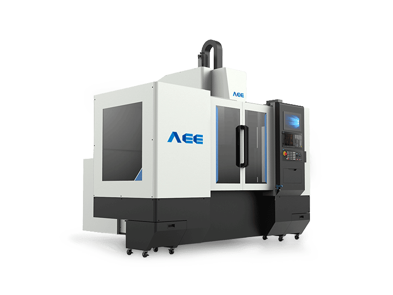
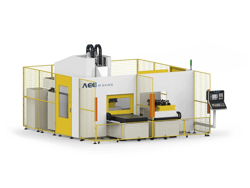
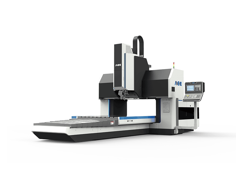
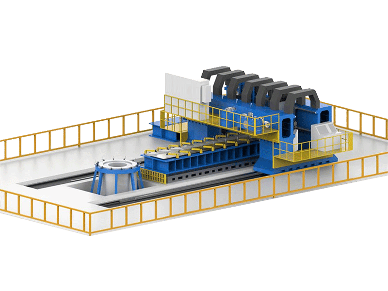
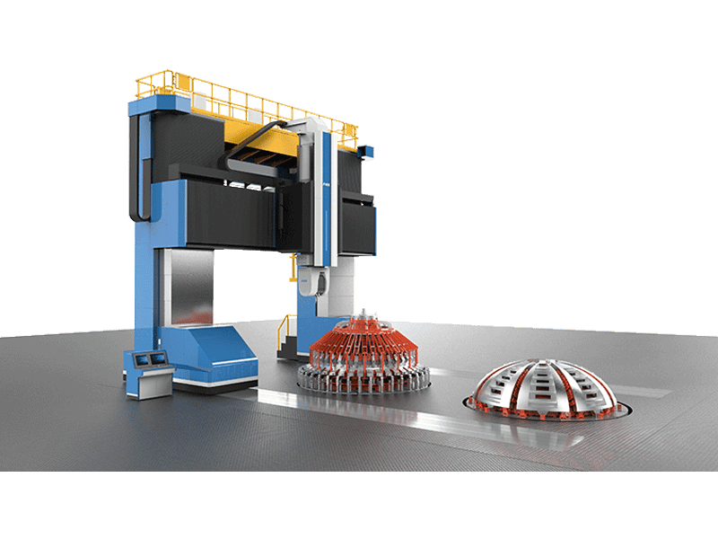
Do not select a machine family from a photograph or a nominal stroke alone. Ask for the Z-axis force available at the welding position, spindle torque at the material-specific rpm, and the repeatability of the axes under load. Those values change the process window more than the overall machine footprint.
If the program includes spot welds on thin aluminum sheet or mixed spot-and-linear joints, evaluate the spot-welding machine class separately.
If spot welding is part of the program, linear FSW machine capacity may not cover the same joint requirements. <Refill Friction Stir Spot Welding (RFSSW)> covers the exit-hole-free variant for visible, sealed, or fatigue-sensitive spot joints.
Choose Force Control or Position Control Based on Process Variability
The control strategy has a direct effect on weld consistency. Force control holds a target axial load and lets the machine adjust the plunge depth as material thickness or fixturing changes. Position control holds a programmed depth and is simpler to set up, but it is less tolerant of thickness variation, workpiece distortion, or fixture deflection.
For thin sheets and tight dimensional parts, position control plus an accurate touch-off routine can work well. For thicker plate, long seams, and materials that soften unevenly during welding, force control is often more stable because it keeps the tool shoulder engaged with controlled pressure. The most flexible configuration offers both modes so the process engineer can choose based on the joint and then monitor spindle torque, force, and position during production.
Confirm how the machine stores and reports process data. For production applications, the ability to record force, torque, temperature, and axis position for each weld can turn a repeating defect into a traceable process problem instead of an operator dispute.
Select Tooling, Fixtures, and Automation as One System
Tooling should be decided during machine selection, not after the order. The pin tool type affects heat input, material flow, exit-hole formation, and the force required from the spindle. Conventional pin tools cover many standard joints, while retractable pin tools eliminate exit holes in closed paths, bobbin tools weld hollow sections without rigid back support, and stationary shoulder tools reduce heat input and improve surface finish on thin sections.
The fixture is part of the welding system. Clamping force, backing plate material, thermal expansion, and access for the tool shoulder must be designed for the actual part. A machine with strong axes will still produce inconsistent welds if the workpiece lifts, deflects, or loses clamping pressure during the weld.
Automation should follow the process, not the other way around. If the cell includes dual worktables, automatic loading, laser tracking, tool changing, or data logging, confirm those options are supported by the controller and the safety architecture. Adding them later can be more expensive than specifying them correctly from the start.
Tool features only reduce risk when the selected machine can command and monitor them correctly. <AEE provides customer with optional features FSW tool> covers optional tool configurations and what to confirm during specification.
Validate the Process Before You Commit
A machine datasheet is not a weld guarantee. The most useful evaluation is a sample weld on the buyer’s own material and geometry, followed by destructive and non-destructive checks that match the production requirement.
Use this validation sequence:
- Send the part drawing, alloy, thickness, joint configuration, weld length, and required cycle time.
- Define the pass criteria before the test, including tensile or bend requirements, macro-section quality, leak or pressure limits, and distortion limits.
- Run the sample weld with the proposed tool, fixture, and backing support.
- Inspect the joint by the agreed method and record the machine parameters, force, torque, and weld speed.
- Use the trial result to confirm the spindle, downforce, control mode, and cycle time before finalizing the configuration.
A trial result supports only the tested part, material, setup, and process conditions. Treat it as evidence of applicability, not as a blanket approval for untested alloys or changed supply.
Send Your Part Requirements for a Feasibility Review
A machine decision is easier when it starts with a real workpiece. Send the alloy, maximum weld depth, joint type, weld length, curvature, production volume, and any leak or strength requirements. Aerospace Engineering Equipment (Suzhou) Co., Ltd. can compare the application against the machine envelope, spindle, force, fixture, and tooling options before you commit to a configuration.
Contact Aerospace Engineering Equipment (Suzhou) Co., Ltd. at [email protected] or +86 18325808715 with your part drawing and target cycle time for a feasibility review and sample weld plan.
FAQ
What is the first specification I should confirm when buying an FSW machine?
Confirm the maximum single-side weld depth in the most demanding material you intend to weld. That requirement drives the Z-axis force, spindle torque, and machine rigidity. Table size is important, but a large table with insufficient downforce will not solve a thick-plate weld problem.
How much spindle power and downforce do I need for aluminum and copper?
There is no single answer because required force depends on alloy, thickness, pin tool, and travel speed. For thin aluminum sections, a 12 kW spindle with 30 kN Z force can cover many 8 mm-class applications. Heavy copper sections may require 200 kN Z force and a spindle above 100 kW with high torque at low speed. Base the decision on a sample weld, not a general material label.
Is a C-type machine suitable for production, or do I need a gantry machine?
A C-type machine can work in production for smaller parts and shorter cycle times, especially with dual worktables. A gantry machine becomes more relevant for large panels, long seams, or high-force welds that require a larger working envelope and more stiffness. Choose by part size, weld length, and force requirement, not by machine name alone.
How important is sample welding before purchasing an FSW machine?
It is the most important validation step. A sample weld confirms that the machine, tool, fixture, and process parameters work together on your actual material and geometry. It should include agreed destructive or non-destructive checks and the recorded welding data, so the result can be used to justify the final specification.
Can one FSW machine handle both butt welds and spot welds?
Linear FSW machines are not automatically suitable for friction stir spot welding. Spot welding uses a different tool, axis motion, and force sequence. If a program requires both, specify separate machine capability or evaluate whether a dedicated FSSW cell is more effective than forcing one platform to perform two different processes.
If you’re interested, check out these related articles:
AEE attend 13th International Symposium on FSW in Kyoto, Japan on 21 – 23 May 2024
Refill Friction Stir Spot Welding (RFSSW)