
Guide to Friction Stir Welding for 5G Base Station Cooling Plates
Table of Contents
- Why 5G Cooling Plate Sealing Cannot Be Treated as Ordinary Aluminum Welding
- Channel Design and Material Selection for FSW Cooling Plates
- Process Window for Sealed Channel Welds
- Machine, Fixture, and Tool Requirements for Cooling Plates
- Inspection and Leak Qualification
- Scaling From Prototype to Production
- Next Step for Cooling Plate Process Qualification
- FAQ
- Which aluminum grades are suitable for FSW cooling plates?
- Can FSW weld very thin cooling plate covers without burn-through?
- What causes a cooling plate weld to leak?
- How should a production line inspect FSW cooling plates?
Friction stir welding for 5G base station cooling plates is a solid-state joining process that seals thin aluminum channel covers without filler metal, shielding gas, or fusion-weld porosity. A rotating tool plasticizes material below its melting point and forges a narrow seam along the channel webs. For a cooling plate, that seam is also a thermal and hydraulic boundary: it must keep coolant inside, hold the cover flat against the heat source, and remain stable through years of outdoor thermal cycling. This guide explains the design, process control, tooling, fixturing, and inspection practices that make FSW a repeatable production route for sealed aluminum cooling plates.
Why 5G Cooling Plate Sealing Cannot Be Treated as Ordinary Aluminum Welding
A 5G base station cooling plate looks simple: an aluminum plate with internal channels and a cover. The difficulty is that every channel wall is a potential leak path, and the welded seam must sit on a narrow land without collapsing the channel or distorting the interface surface. Fusion welding adds enough heat to create porosity, hot cracking, and large distortion on thin sections. Brazing can seal the channels, but it introduces an additional interface and is sensitive to surface preparation and flux residues. FSW operates in the solid state, so it avoids porosity that forms from solidification and limits the amount of heat absorbed by the thin cover.
The design also has a flatness problem that is easy to underestimate. Even local distortion around a welded channel can reduce contact between the cooling plate and the power amplifier or heat-generating board above it. In service, that creates hot spots before any visible leak appears. A stable FSW process keeps the plasticized zone small and uses controlled axial force, which is why the weld can be placed close to functional surfaces while maintaining post-weld flatness.
Channel Design and Material Selection for FSW Cooling Plates
The most practical FSW cooling plate design starts with the welding path, not only with the coolant flow path. Each seam must have enough solid land under the tool shoulder, a consistent material thickness, and a straight or gently curved route. A narrow land can collapse under axial force. A blind or sharply changing path makes tool control and exit-hole management more difficult.
Common material choices include 6xxx-series alloys such as 6061 and 6063 because they machine well, conduct heat effectively, and respond predictably to FSW. 5xxx alloys can also be used where higher formability or corrosion resistance is needed. The heat-affected zone around the weld may soften in heat-treatable 6xxx alloys, but for a cooling plate the main risk is usually leakage and dimensional change rather than loss of bulk tensile strength. If the part must be re-heat-treated after welding, that step should be planned before fixing post-weld flatness.
| Design factor | What to specify | Why it matters |
|---|---|---|
| Seal land width | Minimum full-width land under the shoulder | Prevents channel wall collapse and side flash |
| Cover thickness | Remaining wall above the channel | Controls penetration tolerance and pressure capability |
| Weld path | Straight or continuous curve along each web | Simplifies programming and exit-hole strategy |
| Flatness allowance | Post-weld machining allowance | Compensates for small distortion without changing thermal contact |
| Exit strategy | Run-off tab, dual-side access, or retractable tool | Removes the keyhole from the functional sealing path |
Process Window for Sealed Channel Welds
The goal is enough heat to plasticize material through the cover without pushing softened aluminum into the coolant channel. The key inputs are spindle speed, travel speed, and axial force, with tool tilt where the machine allows it. The relationship between them matters more than any single setting. Higher travel speed can improve productivity, but it changes heat input, surface finish, and the exit hole. For a thin cover, lower heat input from a smaller shoulder or stationary-shoulder tool can preserve wall thickness and reduce flash.
Force control is especially important. Position control alone can allow small changes in material thickness, fixture deflection, or tool wear to move the pin depth. That changes penetration and can create a root flaw opening into a channel. Force control, or a closed-loop system that records force, torque, and temperature, helps prove that each weld stayed inside the same process envelope.
Machine, Fixture, and Tool Requirements for Cooling Plates
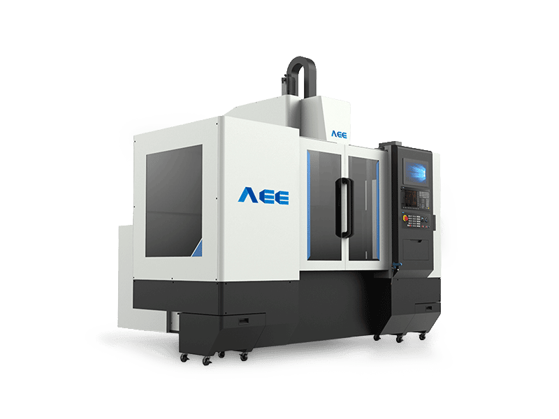
The machine must be stiffer than the workpiece. Cooling plate channels create many short weld passes with tool plunging and retracting, so the Z-axis must hold depth repeatably while the worktable keeps the entire panel flat. A C-type machine is often suitable for base station cooling plates because the components are plate-shaped and the working envelope can match the panel size.
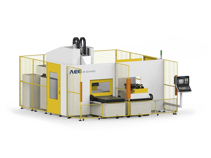
For production, a dual-worktable configuration separates welding time from loading time. While one fixture is being welded, the operator or robot prepares the next plate. This matters for cooling plate lines because the weld time per plate can be shorter than the time needed to clean, load, clamp, and record the part. Machine selection should also include a tool and spindle interface that can carry the required speed and torque without overheating during repeated short passes.
| Requirement | What to check | Why it matters |
|---|---|---|
| Z-axis stability | Repeatability under welding force | Keeps penetration outside the channel wall |
| Worktable flatness | Full support across the plate | Prevents local bending and channel wall thinning |
| Force data logging | Recorded force, torque, and position | Supports qualification and defect isolation |
| Loading method | Dual-worktable or automated handling | Keeps utilization high when pass time is short |
Fixturing is the hidden half of the process. The cooling plate must be clamped close to each weld path and supported evenly from below. A gap between the plate and backing allows material to deflect under the tool, producing incomplete root consolidation or excessive flash. Spot clamps alone are usually not enough. A machined backing plate or vacuum bed with consistent support along the channel lands reduces variation.
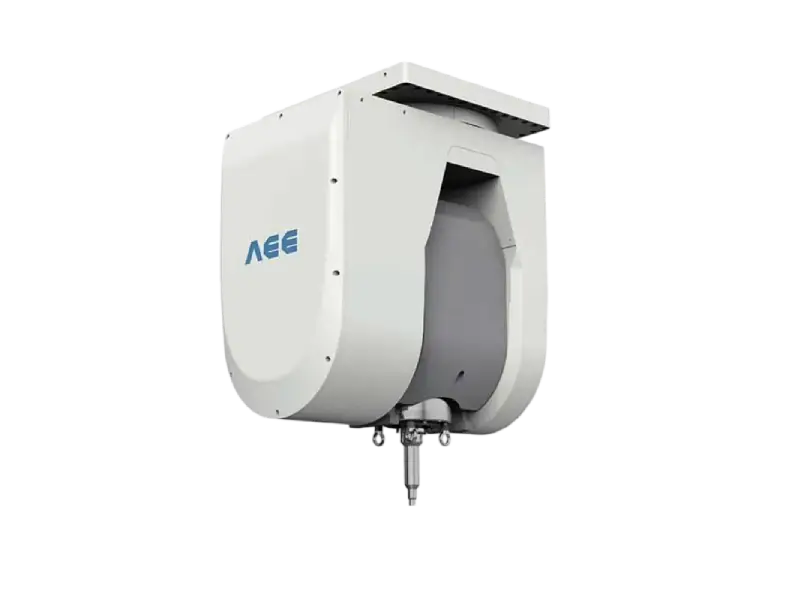
Tooling selection is part of process development, not an interchangeable accessory. The pin length, shoulder diameter, and material all influence heat generation, material flow, and tool life. A conventional tool is a practical starting point for straight channel seals. If the cover is very thin or the application cannot tolerate flash, a stationary-shoulder style may produce a better surface with lower heat input. The tool exit strategy must also be defined before the design is frozen.
Inspection and Leak Qualification
Inspection should be built in three layers. The first is visual and dimensional. The weld should show a smooth surface with no open path, flash indicating excessive plunge, or discoloration suggesting overheating. Plate flatness and channel cover thickness should be recorded at fixed positions.
The second layer is destructive or semi-destructive process qualification. A sample plate from the same material and fixture can be sectioned across the weld to confirm that the root passes through the intended land without filling the channel. Macrographs reveal tunnels, voids, and root flaws that cannot be seen from the surface.
The third layer is leak testing, which is the final acceptance gate for the intended function. Pressure decay or helium testing should use the same pressure range and hold time as the production specification, not only a quick bubble test. A traceability record linking each plate to its weld parameters, fixture version, tool serial number, and leak result turns a successful sample into a repeatable production method.
Scaling From Prototype to Production
A successful lab weld does not automatically mean a stable production line. Before high-volume supply, the process should be proven on a representative batch that includes the production fixture, the actual tool life window, the planned machine, and the same post-weld machining. This is the point to confirm process limits: how many welds a tool can run before penetration shifts, how often the fixture should be cleaned, and whether the parameter window remains acceptable across material lots.
For manufacturers building many cooling plate variants, automation can be added without replacing the process. Dual-worktable machines, automatic tool changers, and data logging allow the same qualified weld parameter set to be called up per part number. The qualification effort stays reusable as long as the material, joint geometry, and machine boundary conditions are not silently changed.
Next Step for Cooling Plate Process Qualification
For a new 5G cooling plate, the most useful next step is to send the current channel drawing or a sample along with the operating conditions: coolant pressure, thermal cycling requirement, production volume, and allowable post-weld distortion. With those inputs, an FSW supplier can confirm whether the design can be welded, define the tool path and exit strategy, and plan a sample welding trial before machine investment.
Contact Aerospace Engineering Equipment (Suzhou) Co., Ltd. at [email protected] or +86 18325808715.
FAQ
Which aluminum grades are suitable for FSW cooling plates?
6xxx alloys such as 6061 and 6063 are common because of machinability, thermal conductivity, and predictable FSW response. 5xxx alloys are also weldable and may be chosen for corrosion or formability requirements. The material choice should be fixed before tool and parameter development because heat input, tool geometry, and post-weld properties change between alloys.
Can FSW weld very thin cooling plate covers without burn-through?
Yes, that is one of its main advantages. The process does not rely on melting, so the cover is not exposed to an arc or weld pool. Penetration is controlled by pin depth and axial force. With suitable tooling and a flat backing plate, thin covers can be welded with limited distortion, but the fixture must support the cover directly under the weld.
What causes a cooling plate weld to leak?
Common causes include incomplete root consolidation, a pin depth that briefly breaks into the coolant channel, a collapsed channel land, or an exit keyhole left on a functional seal path. Most of these failures come from the fixture, path programming, exit strategy, or tool wear rather than from one incorrect spindle setting.
How should a production line inspect FSW cooling plates?
Use layered inspection. At the weld development stage, section samples to confirm the root position. In production, record the weld parameters for each plate and perform a leak test at the production pressure and hold time. Visual checks and dimensional measurements add information, but they should not replace a functional leak test.
If you’re interested, check out these related articles:
Refill Friction Stir Spot Welding (RFSSW)
AEE provides customer with optional features FSW tool
Customized Dissimilar Material Welding Manufacturers in China