
Gantry FSW Machines: Specs and Layout for Large Panels
Table of Contents
- Where a gantry FSW machine fits in a large panel line
- Gantry machine specifications that decide whether your panel fits
- What the published ratings prove and what they do not
- Where the 1D and 2D models divide
- Panel size against worktable size and the margin that matters
- Floor space, foundation and the loading path
- Matching spindle force and torque to panel thickness
- Workholding, backing support and distortion control
- Throughput options for gantry layouts
- What to put in an RFQ for a gantry FSW machine
- Send the panel envelope with your enquiry
- FAQ
- How much floor space does a gantry FSW machine need?
- Can a gantry FSW machine weld curved panels?
- What is the maximum aluminium thickness on a gantry machine?
- Do I need a retractable tool on a gantry machine?
- How long does a 3 metre seam take?
A gantry FSW machine is the answer when the panel is too large to move and the seam has to stay straight over several metres. The bridge carries the welding head across a fixed table, so the workpiece stays clamped while the head travels, and frame stiffness rather than operator skill decides whether the seam holds tolerance. The specifications that decide fit are the worktable and stroke envelope, the thickness and force ceiling, and the floor and loading space around the machine. This guide works through each one against published gantry data, including where a C-type, extra-length or heavy-load machine is the better starting point.
Where a gantry FSW machine fits in a large panel line
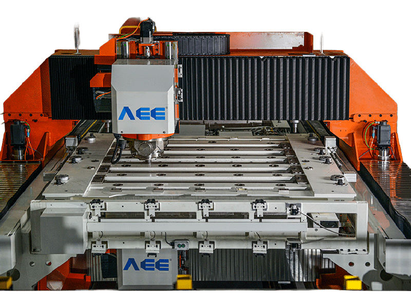
A gantry machine supports the welding head on a beam that spans the table and is carried by two columns. Axial force from the tool passes down through the beam and the columns into the foundation, instead of through a frame that also has to reach around the workpiece. That is why a gantry can be built wide: the span is fixed at the design stage and the structure is sized for the force at the widest point of travel.
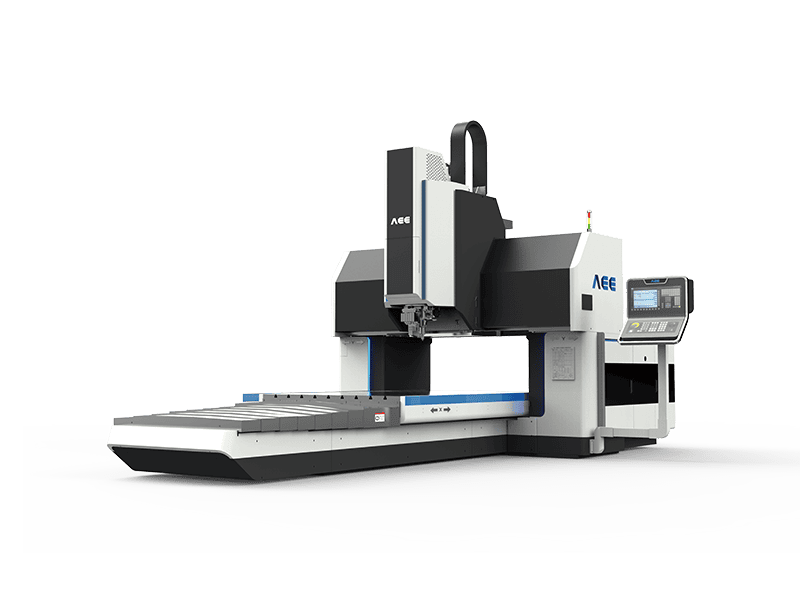
The second consequence is that the workpiece does not move. A four metre aluminium panel stays clamped while the head travels, so the fixture only has to hold position rather than also carry the panel through the motion. Clamp design becomes a question of holding the seam straight, not of surviving acceleration.
Not every large part wants a gantry. A long, narrow profile is better served by a machine built around a long X stroke, and a very thick section needs a frame sized for force rather than for travel. The table below separates the families on the two variables that decide most projects: available width and thickness ceiling.
| Machine family | Worktable, width by length | Maximum welding thickness | Typical panel task | Do not choose it when |
|---|---|---|---|---|
| C-type (AEE FSW 8×10/2) | 600 mm by 1200 mm | 8 mm | Cooling plates, small housings, short straight seams | The panel is wider than the table, or a continuous seam is longer than the table length |
| Gantry, 1D (AEE FSW 25×40/1) | 2500 mm by 4000 mm | 25 mm | Wide base plates and floor panels welded in straight lines | The seam closes on itself or follows a contour |
| Gantry, 2D (AEE FSW 8×30/2) | 2000 mm by 3000 mm | 8 mm | Curved or contoured panels in thin to medium section | The section is thicker than 8 mm, or the seam runs the full stroke with no room for tabs |
| Extra-length straight profile (AEE FSW 8×160/1) | Narrow table, 16000 mm X stroke | 8 mm | Long rail body profiles and stringers | The workpiece is wide; this table suits long straight sections |
| Heavy load (AEE FSW 100×100/2) | 3000 mm by 8000 mm | 100 mm aluminium from one side, 35 mm copper | Thick plate for aerospace and ship structures | The section is under 25 mm and the building cannot carry a 120 t machine |
The dividing line between these families is width and thickness together, not length alone. A 6 m part under 1.2 m wide may be cheaper on an extra-length machine, while a 2 m wide plate is gantry territory even at a modest length.
Gantry machine specifications that decide whether your panel fits
The gantry line from Aerospace Engineering Equipment (Suzhou) Co., Ltd. (AEE) is published in four models that differ in table size, thickness ceiling, axis count and force. Reading them side by side shows which specification actually binds a project.
| Model | Worktable, width by length | Maximum welding thickness | Weld dimension | X and Y stroke | Spindle speed, torque, power | Maximum Z force | Overall dimensions and weight |
|---|---|---|---|---|---|---|---|
| AEE FSW 16×8/1 | 800 mm by 1000 mm | 16 mm | 1D | X 800 mm, Y 600 mm | 2500 rpm, 160 Nm, 17 kW | 50 kN | 2500 by 2000 by 2700 mm, 10000 kg |
| AEE FSW 25×40/1 | 2500 mm by 4000 mm | 25 mm | 1D | X 4000 mm, Y 2500 mm | 2000 rpm, 257 Nm, 31 kW | 60 kN | 10000 by 7000 by 3200 mm, 30000 kg |
| AEE FSW 8×25/2 | 1800 mm by 2500 mm | 8 mm | 2D | X 2500 mm, Y 1700 mm | 4000 rpm, 112 Nm, 12 kW | 30 kN | 7000 by 5000 by 2900 mm, 14000 kg |
| AEE FSW 8×30/2 | 2000 mm by 3000 mm | 8 mm | 2D | X 3000 mm, Y 2000 mm | 4000 rpm, 112 Nm, 12 kW | 30 kN | 9000 by 6000 by 3000 mm, 18000 kg |
What the published ratings prove and what they do not
A specification sheet is a screening tool. It tells you which models to ask about, not what your part will do. The difference matters when the purchase order is written.
| Record | Method context | Responsible use | Do not infer |
|---|---|---|---|
| AEE FSW 25×40/1 rated at 25 mm maximum welding thickness | Company datasheet, aluminium, 1D | Screening whether a 20 to 22 mm aluminium panel sits inside the model’s stated envelope | That the same model reaches 25 mm in 7xxx or in copper, or that 25 mm is achievable at the rated feed rate |
| Gantry line highlights quoted up to 5000 mm per minute and 8 mm in 6XXX | Company product information, line level | Asking for the quoted speed and depth for your model, alloy and joint | That every model in the family reaches either figure, or that the rate holds on a 2D contour |
| Spindle AEE-S064 at 1000 rpm, 874 Nm and 200 kN | Company spindle datasheet | Checking that the spindle can carry the force your section needs | That fitting this spindle raises machine capacity; the gantry structure, table and fixture must carry the same force |
Where the 1D and 2D models divide
Two of the four models weld in one dimension only. The 16×8/1 and 25×40/1 are 1D machines, while the 8×25/2 and 8×30/2 carry a C axis rotating through 360 degrees at 10 rpm and are rated for 2D work. If the seam follows a contour, a 1D model is the wrong starting point regardless of how large its table is.
The thickness figure is tied to the alloy as well. A rating stated for aluminium does not transfer to copper, and within aluminium it does not transfer between 6xxx and 7xxx without a welding trial, because flow stress and hot-cracking sensitivity differ.
Joints that mix material families raise a separate set of tool and parameter questions. <Customized Dissimilar Material Welding Manufacturers in China> covers customized welding programmes for dissimilar metal combinations.
Panel size against worktable size and the margin that matters
Plan from the stroke, not the table. On three of the four gantry models the X stroke equals the table length, so the tool centre can reach the table end and stops there. The part therefore has to give up length before the machine does.
A seam cannot start and end at the extreme of travel. The tool needs a short run-on before the pin reaches full engagement and a run-off after the seam is complete, and those zones must sit on material you are willing to scrap. If the part already fills the stroke, there is nowhere to put them. A 2900 mm seam on the 8×30/2 leaves 100 mm in total across both ends. How much tab length a tool needs depends on shoulder diameter and the parameter ramp, so confirm the figure rather than assume it.
The same logic applies across the table. On the 25×40/1 and 8×30/2 the Y stroke matches the table width, and clamps, stops and the fixture frame all sit inside that envelope. Usable panel width is the Y stroke minus whatever the fixture takes, which on a heavy panel is often 150 mm or more per side.
On the 2D models, add head clearance. The head rotates about the tool axis and tilts to hold the welding angle, and the head body sweeps a larger circle than the tool itself. Clearance behind the tool has to be checked on the machine drawing, not estimated from the tool diameter.
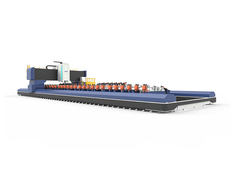
Where the seam is simply longer than any gantry table, the extra-length family is the direct answer: a 16000 mm X stroke on a narrow table, built for rail body profiles and long stringers.
Floor space, foundation and the loading path
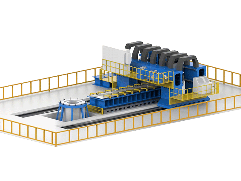
Overall dimensions include the gantry frame, not just the table. The 25×40/1 measures 10000 by 7000 by 3200 mm and weighs 30000 kg, while the heavy-load 100×100/2 measures 25000 by 8000 by 3500 mm at 120000 kg. The height figure sets the minimum clear height, and the crane hook still has to pass above the machine when a panel is lifted in.
The footprint is the space the structure occupies; the working space around it is larger. Loading direction matters more than total area. End loading needs clear floor at one end of the stroke, side loading needs it along the table, and the choice determines whether the crane picks the panel up once or twice per cycle.
A machine that pushes 60 kN into the work also pushes it back into the floor. The 25×40/1 is rated at 60 kN maximum Z force and the heavy-load machine at 200 kN, and that load is cyclic. A standard industrial slab is not the design basis for either case, so ask for the foundation drawing before the concrete is poured and keep the machine mass separate from the dynamic force in the structural calculation.
The heavy-load machine is also built to let the workpiece pass through rather than be lifted over: a passable width of 4500 mm and a passable height from 644 mm to 1144 mm mean the gantry straddles the part, and the crane only has to set it down.
Services are modest by comparison. Compressed air is specified at 0.6 MPa to 0.8 MPa at 1 cubic metre per minute through a phi 8 connection across the range, which is a small line item next to the floor and crane requirements.
Matching spindle force and torque to panel thickness
Axial force rises with section thickness because the tool has to move a larger volume of plasticised material. Torque rises with both force and tool radius. Rotation speed falls as thickness rises, because heat generated per unit length has to stay inside a window the alloy tolerates. The spindle therefore has to deliver high torque at low speed for thick plate and high speed at modest torque for thin sheet, and those are different machines.
The spindle range for this machine family spans both ends. The AEE-S125 covers 1 mm to 8 mm at up to 4000 rpm, 112 Nm and 30 kN, while the AEE-S064 covers 2 mm to 100 mm at up to 1000 rpm, 874 Nm and 200 kN. Between them sit the S119 at 12 mm, the S112 at 16 mm, the S065 at 25 mm and the S076 at 40 mm, stepping torque and force upward as the thickness ceiling rises.
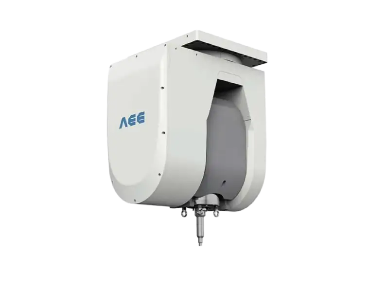
The spindle is one element in a load path, not the whole of it. A 200 kN axial force deflects the beam that carries the head, and beam deflection appears as thickness variation along the seam rather than as a visible machine fault. That is why the heaviest machine in the range uses a double gantry structure instead of a single beam, and why a force rating is a structural statement as much as a spindle one.
A practical check when comparing models is to read maximum Z force and spindle torque together. The 25×40/1 pairs 257 Nm and 31 kW with 60 kN of Z force; the 8×30/2 pairs 112 Nm and 12 kW with 30 kN. If a supplier offers a large spindle on a light frame, the frame number is the one that limits the weld.
Workholding, backing support and distortion control
On a large panel the fixture decides whether the seam stays where the drawing puts it. Clamping force has to seat the panel against the backing bar without buckling it, and clamp positions should work outward from the seam so material is pushed toward the joint rather than stretched away from it.
Conventional FSW needs a rigid backing bar under the seam, with a groove or anvil that lets the pin penetrate slightly past the root. The bar wears, and a worn bar shows up as root defects rather than as a visible machine change, so it belongs on the maintenance list with a periodic wear check.
A bobbin tool removes the backing requirement. Two shoulders work on both faces of the joint at once, so hollow profiles and long straight seams can be welded without rigid support underneath, which is why the design is used on rail profiles and barrel seams. The trade-off is access: both sides of the joint must be reachable by the lower shoulder, which rules out a panel sitting flat on a solid table.
Tool choice also changes what the fixture has to do. A stationary shoulder runs with the shoulder sliding on the surface while only the pin rotates, which cuts heat input and produces no flash and no thinning; on thin panels that can remove a post-weld machining allowance. A retractable tool pulls the pin back into the shoulder at the end of the weld and lets plasticised material fill the exit hole, which matters on a closed contour where a keyhole would otherwise need repair.
The tool is a service item with more variants than a first purchase usually assumes. <AEE provides customer with optional features FSW tool> covers the optional tool features available for specific weld requirements.
Before the layout is frozen, weld a coupon on the actual fixture. Clamp positions, backing bar condition and tool choice interact, and a coupon at production thickness on the production fixture is the only way to see them interact before the foundation is set.
Throughput options for gantry layouts
At the published maximum of 5000 mm per minute for the gantry line, a 3000 mm seam takes 36 seconds of arc time. Loading, clamping, tool change and inspection take the rest of the cycle. On most large panel work the arc is not the constraint, so layout decisions that shorten handling return more than a faster spindle ever will.
The first option is a dual station. Two tables or a shuttle let one panel load while the other welds, and the same logic applies to a gantry cell with two fixture positions served by one bridge. The cost is floor space and a second fixture, which for a large panel is not a small item.
The second option is two machines in tandem. Two gantries on adjacent foundations double output without putting both seams through one cycle, at the cost of a second capital commitment and a wider building.
The third option is double-head welding. The double-head FSW machine welds up to 100 mm from one side in aluminium and up to 8 mm from both sides at once at up to 2.5 m per minute, and the fully automatic double-head production line covers 1.2 mm to 16 mm at lengths up to 18.5 m and widths up to 3.5 m.
A second head is not free. The two heads have to stay aligned to each other within the seam tolerance, and the fixture has to locate both seams at once, which is a tighter requirement than locating one. Maintenance also doubles, because there are two spindles, two tool changes and two cooling circuits to keep in condition.
Not every joint needs a continuous seam. Where a stiffener or bracket only has to be fixed in place, a spot process is the cheaper answer and does not tie up a gantry that is needed for long welds.
Spot joining has its own tooling and parameter logic, separate from a linear gantry weld. <Refill Friction Stir Spot Welding (RFSSW)> covers refill friction stir spot welding as a spot joining process.
What to put in an RFQ for a gantry FSW machine
A gantry quotation can only be as specific as the enquiry. These six fields change the model, the fixture or the foundation, and leaving any of them out pushes the decision back to the supplier.
| RFQ field | What to state | Why it matters |
|---|---|---|
| Panel envelope | Maximum length, width and thickness, plus whether the seam is straight or contoured | A seam longer than the X stroke forces a repositioning step that leaves a start and stop mark |
| Alloy and temper | Exact grade and temper, including any dissimilar joint | A thickness rating does not transfer across alloy families or tempers |
| Seam count and closure | Seams per part, closed or open, total weld length | A closed contour needs a retractable tool or a planned exit hole and repair |
| Fixture and loading | Clamp zones, loading direction, available crane capacity | A machine that cannot be loaded is a machine that cannot run |
| Post-weld tolerance | Flatness, angular distortion and seam position tolerance | Drives gantry stiffness, fixture design and whether a second machining pass is needed |
| Acceptance basis | Coupon tests, NDT method, procedure qualification and traceability | The machine specification does not define acceptance; the agreed procedure does |
Reject this line: “Gantry FSW machine, 20 mm aluminium, 3 m panels.”
Replace it with: “Gantry FSW machine for 6061 T6 panels measuring 2900 by 1800 mm at 14 mm thick, two straight seams per part, 30 parts per shift, flatness within 1 mm per metre after welding, with fixture and foundation drawings included in the quotation.”
The quotation answers half the question. The fixture design, the foundation drawing and the acceptance procedure answer the rest, and all three should be settled before the purchase order is signed.
Send the panel envelope with your enquiry
The first page of a gantry enquiry is the part, not the machine. Send the panel envelope in length, width and thickness, the alloy and temper, the number of seams per part and whether each seam is straight or contoured, your fixture and loading constraints, the cycle time you need, and the acceptance method you will apply. Include the flatness and distortion tolerance after welding, because that figure decides how much structure and how much fixture the job needs. We will reply with the model, spindle and layout envelope that fit, or say where the request falls outside the published range.
Dr. Wang Wei
[email protected]
+86 18325808715
FAQ
How much floor space does a gantry FSW machine need?
Start from the overall dimensions, not the table. The 25×40/1 measures 10000 by 7000 by 3200 mm and weighs 30000 kg, while the heavy-load 100×100/2 measures 25000 by 8000 by 3500 mm at 120000 kg. Add clear floor for the loading direction, crane access above the machine and a separate foundation block. The height figure is a minimum clear height, and the crane hook needs space above that.
Can a gantry FSW machine weld curved panels?
Some can. The 16×8/1 and 25×40/1 are rated for 1D work only. The 8×25/2 and 8×30/2 carry a C axis rotating through 360 degrees at 10 rpm and are rated for 2D work up to 8 mm. On a contour, the clearance behind the rotating head has to be checked against the part drawing, not just the tool envelope.
What is the maximum aluminium thickness on a gantry machine?
In this range, 25 mm on the 25×40/1 and 16 mm on the 16×8/1, with the 2D models at 8 mm. Above that, the double-gantry heavy-load family is rated to 100 mm from one side in aluminium and 35 mm in copper. A thickness rating is stated for aluminium and does not transfer to another alloy without a welding trial.
Do I need a retractable tool on a gantry machine?
Only when the seam closes on itself. A retractable tool pulls the pin back into the shoulder at the end of the weld and fills the exit hole, so a closed contour finishes without a keyhole. On an open seam that ends on a run-off tab, a conventional tool is simpler and cheaper to run.
How long does a 3 metre seam take?
At the published maximum of 5000 mm per minute, 36 seconds of arc time. The cycle around it is longer. Loading, clamping, tool change and inspection usually dominate on large panels, which is why a second table or a second head often returns more than a faster spindle.
If you’re interested, check out these related articles:
AEE attend 13th International Symposium on FSW in Kyoto, Japan on 21 – 23 May 2024
Refill Friction Stir Spot Welding (RFSSW)
AEE provides customer with optional features FSW tool