
FSW Process Parameters: How Speed, Force & Tilt Interact
Table of Contents
- What Each FSW Process Parameter Controls
- How Rotation Speed and Travel Speed Together Determine Heat Input
- Why Axial Force and Tilt Control Material Flow
- Common Parameter-Driven Defects and How to Diagnose Them
- A Practical Sequence for Developing FSW Parameters
- Machine Constraints That Define Your Process Window
- What Happens After You Define the Parameters
- Questions Engineers Ask About FSW Parameter Setup
- Is there a single best tilt angle for all aluminum alloys?
- How do I know if my axial force is too high?
- Can I use the same parameters for wrought and cast aluminum?
- We are welding long profiles with variable gap tolerance. What parameter strategy helps?
FSW process parameters do not act as independent settings on a machine panel. Rotation speed, travel speed, axial force, and tool tilt form a tightly coupled system where changing one variable ripples through heat generation, material flow, and joint integrity. In over fifteen years of process development across C-type, gantry, and heavy-load FSW machines, I have seen more welds fail from parameter mismatches than from any material defect. The practical challenge is not understanding what each parameter does in isolation — it is finding the window where all four work together for a specific alloy, thickness, and joint configuration.
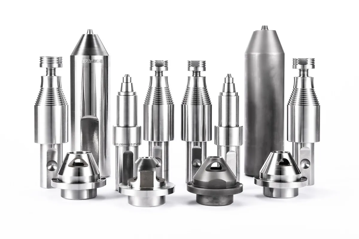
What Each FSW Process Parameter Controls
Before tackling interactions, you need a clear picture of each input. In practice, the four primary parameters set the energy input and material flow regime for the entire weld cycle. Changing any one without adjusting the others often pushes the process outside its stable window within the first 100 mm of weld length.
| Parameter | What It Governs | Typical Indicative Range (6xxx Al, 3–8 mm) |
|---|---|---|
| Rotation speed (rpm) | Frictional heat generation, material shear, and mixing intensity | 600–2,500 rpm |
| Travel speed (mm/min) | Heat input per unit length, cooling rate, and productivity | 200–3,500 mm/min |
| Axial force (kN) | Forging pressure, material consolidation, and contact between shoulder and workpiece | 4–30 kN |
| Tilt angle (degrees) | Shoulder trailing edge engagement, flash formation, and surface finish | 0–3° |
The ranges shift substantially with alloy series. 2xxx and 7xxx aerospace grades often run at lower rotation speeds and higher forces to avoid hot cracking, while 5xxx marine alloys tolerate wider windows. Plunge depth, though often treated as a machine setting rather than a process parameter, also influences the effective shoulder contact area and must be held consistent if force control is not active.
How Rotation Speed and Travel Speed Together Determine Heat Input
These two parameters do not operate independently. Weld pitch — the ratio of travel speed to rotation speed — is the practical variable that governs heat input per unit length. For a given alloy and thickness, too high a pitch starves the joint of heat, producing an unwelded root and tunnel defects. Too low a pitch overheats the material, softens the heat-affected zone, and often leaves a rough, excessively flashy surface.
In a typical 6061-T6 application at 6 mm thickness, a rotation speed of 1,200 rpm with a travel speed of 800 mm/min produces a pitch of approximately 0.67 mm/rev, which reliably generates sufficient plasticity. Doubling travel speed to 1,600 mm/min while holding rotation constant halves the pitch, and temperature near the shoulder drops enough that the probe may stall or plough through insufficiently softened metal. To maintain the heat balance, rotation speed must increase proportionally, but that pushes spindle load and torque demands higher, often exceeding the continuous rating of a 12 kW spindle like the AEE-S125 if the weld requires more than about 112 Nm of torque.
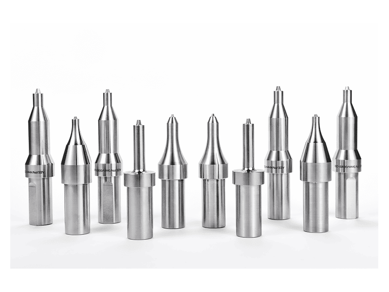
Tool design choices such as shoulder diameter and pin profile directly affect the heat input and force required. <AEE provides customer with optional features FSW tool> covers how optional tool features including cooling channels and coating can extend the process window for specific alloys.
Why Axial Force and Tilt Control Material Flow
While speed settings determine heat, axial force and tilt dictate what the plasticized material does. Axial force is the forging pressure that consolidates the stirred material into the joint line. Insufficient force leaves a subsurface void — material is mixed but not compacted. Excessive force generates flash that expels material, thins the weld zone, and accelerates shoulder wear.
Tilt angle modifies where the axial force is applied. With a 1–2° tilt (trailing-edge-down), the rear of the shoulder digs into the workpiece, creating a pressure gradient that pushes softened metal from the advancing side toward the retreating side and downward into the joint root. Zero tilt is occasionally used with very stiff spindles and stationary-shoulder tools, but for conventional FSW with a single-piece pin tool, losing tilt means losing the directional material transport that fills the root of the weld. I have recovered welds that exhibited intermittent root flaws simply by increasing tilt from 1.0° to 1.8°, without touching speed or force — the additional rear-shoulder engagement completed the material extrusion into the root gap.
The force–tilt combination becomes especially critical with copper or dissimilar joints. Copper demands substantially higher axial force — often 20–40 kN for plates above 10 mm — and tilt above 1.5° can cause shoulder gouging if the underlying backing plate does not provide precise support. On a heavy-load machine like the AEE FSW 100×100/2, which delivers up to 200 kN Z-axis force, holding a stable force setpoint is straightforward, but on lighter C-type frames, the operator must verify that the machine’s stiffness and spindle torque rating align with the required force for the chosen tilt.
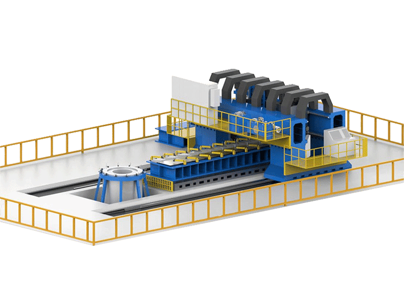
Common Parameter-Driven Defects and How to Diagnose Them
When the process window is violated, defects appear in predictable patterns. The most useful diagnostic skill is mapping a defect back to the parameter balance that caused it.
- Tunnel defects at the retreating-side root almost always trace to insufficient heat or insufficient axial force filling. A tunnel that opens intermittently suggests a mismatch between travel speed and rotation — the pitch is drifting in and out of the stable zone. A continuous tunnel points to a consistent heat deficit: either the rotation speed is too low for the travel speed, or the tilt angle is too small to direct material downward.
- Voids or wormholes along the advancing side often result from excessive travel speed when the probe cannot transport material across the joint line quickly enough. Slowing travel speed while keeping rotation constant often closes the defect, though at the cost of cycle time.
- Flash that forms a continuous ribbon on the retreating side is typically a force or tilt issue. Excessive axial force squeezes material out before it can consolidate. In some cases, reducing force by 10–15% while slightly increasing rotation speed restores balance without sacrificing joint strength.
- Surface galling or tearing near the shoulder indicates insufficient heat, often due to low rotation speed combined with low tilt. The shoulder skids over partially softened material, pulling the surface rather than flowing it.
- Root lack of fill where the probe tip does not fully penetrate is a straightforward parameter error — insufficient plunge depth, too low a force, or too fast a travel speed that lifts the shoulder as the tool traverses.
I have learned to treat the first 300 mm of a weld as a live process signature. A flash inspection and a quick bend test on the exit point, checked against a torque trace logged during welding, usually reveals whether the defect is thermal, mechanical, or both. When we set up a new battery tray program on an AEE double-head gantry machine, running a series of short beads at different force–tilt pairs alongside real-time spindle torque data exposed the exact combination where the tunnel disappeared and torque remained within the 257 Nm headroom of the AEE-S119 spindle.
A Practical Sequence for Developing FSW Parameters
Development time is expensive, so the sequence matters. The following approach reflects how I structure parameter trials on a new component, whether it is a 2 mm water-cooling plate or a 16 mm structural profile.
Start with heat balance, not force. Select a conservative rotation speed (around 1,000–1,200 rpm for 6xxx series) and a travel speed that yields a visible crown of softened material behind the tool. This baseline simply confirms the material is reaching plasticity. Torque readings should be smooth, not oscillating more than ±5% of the mean.
Engage tilt and force together. Set tilt to 1.5° and axial force to a mid-range value appropriate for the thickness — roughly 1.2–1.5 kN per mm of penetration depth for aluminum. Run a short bead and inspect the surface and root. If a tunnel appears, increase force by 0.5 kN increments while holding tilt. If no tunnel but excessive flash appears, reduce force and increase tilt slightly.
Push travel speed until the defect appears. Once a clean weld is established at a slow travel speed, increase speed in 200 mm/min steps until a defect just begins — a faint root irregularity or slight surface roughness. Back off 100–200 mm/min and run a longer bead to confirm stability. This defines the upper edge of the process window for that rotation speed.
Vary rotation speed to expand the window. Repeat steps 2 and 3 at two other rotation speeds (e.g., 800 rpm and 1,600 rpm). Plot travel speed vs rotation speed with the defect-free region mapped. For many 6xxx applications, this window forms a predictable U-shaped envelope where mid-range rotation speeds permit the widest travel speed variation.
Lock parameters with production fixtures. Tooling temperature, clamp rigidity, and backing plate material shift the thermal boundary of the weld. Running final confirmation on the actual production fixture, not a laboratory vice, is essential. I have seen parameter sets validated on a solid backing plate fail on a water-cooled fixture because the heat extraction rate increased sufficiently to drop root temperature below flow requirements.
Machine Constraints That Define Your Process Window
Parameters that look achievable on paper fail on the shop floor when the machine lacks the torque capacity, stiffness, or force resolution to hold them. This is the hidden half of process development that generic parameter tables ignore.
Spindle torque is often the first bottleneck. The AEE-S125 spindle delivers 112 Nm at up to 4,000 rpm, adequate for welding aluminum up to 8 mm at moderate travel speeds. For 25 mm thick 5083 plate, the AEE-S065 with 257 Nm becomes necessary. If your parameter window requires high rotation speed over 2,000 rpm at high torque, the spindle’s power curve must be checked — torque typically drops off at the upper end of the speed range.
Axial force capacity limits how aggressively you can forge the weld. A C‑type machine like the AEE FSW 8×10/2 with 30 kN Z‑axis force handles most aluminum below 8 mm, but for 16 mm 7075 requiring 50 kN, the AEE FSW 16×8/1 gantry machine with a 50 kN rating is the minimum. Running near the machine’s force ceiling leaves no headroom for process upsets; a slight increase in material hardness or a drop in preheat can push force demand above capacity, triggering a spindle stall and a scrapped part.

Frame rigidity influences how precisely tilt is maintained. Less rigid structures deflect under load, eroding the actual tilt angle at the tool tip. A gantry machine with a heavy cast frame typically holds deflection under 0.05 mm at full load, preserving the tilt you set at the pendant, whereas lighter machine designs may shift 0.1–0.2 mm, enough to alter root fill quality. If you are developing parameters on a well-fixed development machine and then transitioning to a lighter production unit, expect to re-verify force and tilt settings at the production floor.
For applications requiring joining of different material pairs, the process window narrows substantially. <Customized Dissimilar Material Welding Manufacturers in China> details how manufacturers design custom parameter development programs for aluminum-to-copper and aluminum-to-steel joints, where force, heat input, and intermetallic control must be balanced within tight margins.
What Happens After You Define the Parameters
Locking a parameter recipe on a development machine is only the first step. The parameters must survive batch-to-batch variability in material, tool wear, and fixture temperature. We log spindle torque, X‑axis force, and thermal profile on every production run to catch drift before it becomes a defect. When torque rises by more than 8% from the qualified baseline on the same recipe, the tool shoulder is typically wearing, effectively changing the tilt contact condition — and the parameter recipe needs to be re-verified with a fresh tool. This discipline is more important than the initial parameter discovery, yet it receives far less attention in most process guides.
If the machine offers force-control mode alongside position control, the parameter approach shifts. In force control, the Z-axis servo adjusts position to maintain a constant forging force, which can compensate for minor thermal expansion or fixture compliance. However, force control requires a responsive servo loop and low mechanical backlash; on machines with high inertia or lead-screw-driven Z axes, position control with a fixed plunge depth often produces more repeatable results. I recommend force control for thick welds above 10 mm where thermal buildup changes the effective plunge depth during the weld, and position control for thin-gauge welds under 3 mm where maintaining exact pin depth is critical to avoid thinning.
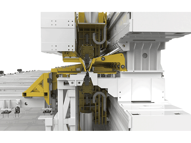
If your program involves material combinations or thicknesses outside the typical aluminum range — such as copper busbars or 100 mm aluminum sections — it is worth confirming the machine’s spindle torque, Z‑force, and frame rigidity before committing to a parameter development plan. Send your part number and thickness requirements to [email protected] or reach our engineering team at +86 18325808715, and we can advise on the machine platform that fits your process window.
Questions Engineers Ask About FSW Parameter Setup
Is there a single best tilt angle for all aluminum alloys?
There is not. A tilt of 1.5° works well for most 6xxx alloys in the 4–12 mm range, but 2xxx and 7xxx alloys often benefit from 1.0–1.2° because lower tilt reduces the shear stress component that can initiate micro-cracking along the advancing edge of the weld. For thin sheet below 2 mm, running at 0° with a stationary-shoulder tool is common. The selection also depends on shoulder diameter; larger shoulders generate more friction and may need less tilt to direct material downward.
How do I know if my axial force is too high?
Excessive axial force expresses itself as heavy flash on both sides of the weld, a noticeable thinning of the joint by 10–15%, and sometimes a concave surface profile behind the shoulder. You can also detect it from the spindle torque trace, which will climb as the shoulder digs deeper, even if rotation and travel speed are unchanged. Reducing force in 2–3 kN increments while checking surface finish and sectioning the weld usually reveals the sweet spot where flash drops to an acceptable level without opening a root defect.
Can I use the same parameters for wrought and cast aluminum?
No, cast aluminum introduces porosity and silicon particles that change thermal conductivity and flow behavior. Cast grades often demand 15–20% higher axial force to collapse porosity and a slightly slower travel speed to allow the material time to flow around the non-uniform solidified structure. Preheating the plate to 100–120°C can reduce the force penalty, but the process window remains narrower than for wrought alloys of the same designation.
We are welding long profiles with variable gap tolerance. What parameter strategy helps?
For intermittent gap variation, force control with a generous upset is effective because the tool self-adjusts to maintain forging pressure as the gap opens or closes. In position control, you must program additional plunge depth margin to accommodate the maximum expected gap, which risks excessive thinning on sections where the gap is tight. If the gap exceeds 10% of plate thickness, parameter tuning alone cannot compensate; the upstream fit-up tolerance or fixture clamping must be improved first. Share your profile drawings and gap specification to [email protected], and we can recommend a fixture concept that narrows the gap before you invest in a tooling cycle.
If you’re interested, check out these related articles:
Customized Dissimilar Material Welding Manufacturers in China
AEE attend 13th International Symposium on FSW in Kyoto, Japan on 21 – 23 May 2024