
FSW Maximum Weldable Thickness: 100mm Aluminum, 35mm Copper
Table of Contents
- What Determines Maximum Weldable Thickness in FSW?
- Why Does Aluminum Reach 100 mm Single Side but Not More?
- How FSW Machine Specifications Translate to 100mm Aluminum and 35mm Copper
- What Limits Maximum Weldable Thickness in Copper to 35 mm?
- How to Verify Maximum Weldable Thickness Claims Before Ordering
- What Engineers Ask About FSW Thickness Capability
- Can FSW weld aluminum thicker than 100 mm?
- Is 100 mm aluminum capacity single-side or double-side?
- Why is copper limited to 35 mm on the same machine that welds 100 mm aluminum?
- Can a small C-type machine weld 35 mm copper with a special tool?
- What should I send to confirm thickness feasibility for my part?
FSW maximum weldable thickness is not a fixed value that transfers from one machine specification to another. It is a boundary set by spindle torque, axial force, tool geometry, and workpiece restraint. For production equipment, we treat 100 mm single-side aluminum and 35 mm single-side copper as practical upper limits backed by heavy-load machine data, not theoretical possibilities. The gap between a machine that reaches those numbers and one that only lists them on a datasheet usually appears only when you examine the force path, spindle duty, and fixture stiffness.
What Determines Maximum Weldable Thickness in FSW?
Maximum weldable thickness in FSW comes down to four interacting limits. Pin length is the first obvious one. The tool must penetrate nearly the full joint depth without breaking through the back face. Spindle torque is the second. As thickness increases, the volume of material being plasticized rises, and the required torque climbs faster than the depth increase alone would suggest. Axial force is the third. Thick sections need enough downward force to keep the shoulder in contact and to forge the root without lifting the workpiece. Fixture stiffness is the fourth and most often underestimated limit. If the backing plate deflects or the clamps yield, the machine may be capable of the depth but the part will still show incomplete penetration or a tunnel defect.
In practice, machines are not rated by depth alone. A C-type unit with 30 kN Z-axis force and 112 Nm spindle torque can handle aluminum up to about 8 mm. A gantry machine with 60 kN and 257 Nm reaches about 25 mm. Moving from 25 mm to 100 mm requires spindle torque near 870 Nm and Z-axis force of 200 kN. Those are not incremental upgrades. They require a different bed structure, a larger spindle, and a power system sized for sustained heat generation.
Why Does Aluminum Reach 100 mm Single Side but Not More?
Aluminum reaches 100 mm before hitting a practical ceiling because the material conducts heat away from the weld so quickly that the root and the crown stop sharing the same thermal condition. At shallow depths the shoulder dominates the heat input. At 100 mm the pin must carry enough energy to keep the bottom of the joint in viscoplastic flow while the surface remains stable. The correction is to slow travel speed, increase shoulder contact area, and use a spindle that can hold high torque without overheating. At some point that tradeoff stops working. The center of the nugget cannot reach a stable state before the adjacent plate mass pulls the heat out.
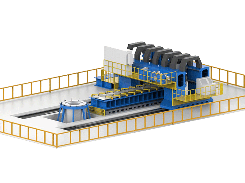
On our heavy-load platform for 100 mm aluminum single-side work, the machine uses a 105 kW spindle with 872 Nm torque and 200 kN maximum Z-axis force. The worktable measures 3000 mm by 8000 mm, and the gantry permits passable heights from 644 mm to 1144 mm. Those figures matter because they describe the full system, not only the spindle. A lighter frame would deflect enough at 200 kN to shift the effective tool position during the pass. The bed mass, the column spacing, and the fixture reaction all play a role in keeping the pin at the programmed depth along a 10,000 mm X-axis stroke.
How FSW Machine Specifications Translate to 100mm Aluminum and 35mm Copper
The jump from medium to thick section capacity is best read as a machine-class comparison. The table below shows three production platforms, with the heavy-load machine carrying the 100 mm aluminum and 35 mm copper ratings.
| Machine class | Maximum aluminum single side | Maximum copper single side | Spindle torque | Z-axis force |
|---|---|---|---|---|
| C-type FSW 8×10/2 | 8 mm | not rated | 112 Nm | 30 kN |
| Gantry FSW 25×40/1 | 25 mm | not rated | 257 Nm | 60 kN |
| Heavy-load FSW 100×100/2 | 100 mm | 35 mm | 872 Nm | 200 kN |
Spindle torque rises from 257 Nm on the 25 mm gantry to 872 Nm on the 100 mm heavy-load machine. Z-axis force climbs from 60 kN to 200 kN. That step is not linear with depth. Aluminum depth quadruples, while torque and force rise by roughly 3.3 to 3.4 times. The table also shows why copper cannot be extrapolated from an aluminum rating. Copper is listed only on the heavy-load class because the process window is much narrower and the thermal load is different.
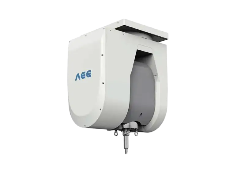
The spindle is only one part of the thickness equation. At these loads, the tool holder and the pin assembly are part of the machine stiffness chain. Standard BT50 holders do not bend the same way as the BT60 holder used on the 100 mm spindle. A long pin in a less rigid holder can deflect, move the nugget off-center, and leave lack of penetration at the root. For thick-section review we ask for the spindle-tool assembly bending behavior, not only the spindle power curve.
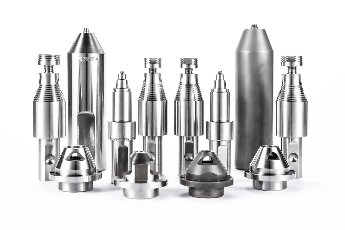
For thick-section work, <AEE provides customer with optional features FSW tool> covers how pin geometry and cooling channel options change the balance between tool life and penetration at the root.
If your program involves aluminum above 40 mm or copper above 20 mm, confirm the spindle-tool assembly and fixture deflection data before finalizing your machine specification. Send your joint thickness, alloy grade, and seam length to [email protected] and we can check the configuration against your part.
What Limits Maximum Weldable Thickness in Copper to 35 mm?
Copper stops earlier because it is not the same thermal problem as aluminum. Copper has higher density, a higher melting point, and far higher thermal conductivity. The process window becomes narrow: the weld must reach a high enough temperature to soften the copper, while the surrounding plate conducts heat away so quickly that the spindle must maintain high power for a long dwell. Tool wear becomes the controlling variable. At 35 mm single-side depth, a worn pin profile can create a tunnel at the root that is difficult to detect in a thick section.
Dissimilar material programs involving aluminum and copper create an even tighter process window, and <Customized Dissimilar Material Welding Manufacturers in China> covers how suppliers manage intermetallic control and tool life in production runs.
Thirty-five millimeters is not a machine frame limit. The same 200 kN and 872 Nm platform that reaches 100 mm in aluminum is rated for 35 mm in copper. The difference is the process window. Buyers often assume that thick aluminum experience transfers to thick copper. It does not. Copper demands slower travel, a different tool material evaluation, and more frequent tool inspection. Once the heat input rises enough to sustain a deeper copper weld, the tool surface condition becomes the limiting factor before the machine runs out of force.
Part geometry adds another layer. A 35 mm copper plate with a wide backing bar welds more predictably than a copper structure that changes section along the seam. In thick parts, the thermal mass ahead of the tool and behind it changes the cooling rate as the weld progresses. Force control and data acquisition cannot completely fix a part that steps from 20 mm to 35 mm mid-seam. The fixture must hold the material without letting the root open up under thermal expansion.
How to Verify Maximum Weldable Thickness Claims Before Ordering
Maximum weldable thickness is only meaningful when the alloy, joint type, welding position, and acceptance standard are attached to the number. Before accepting a supplier’s rating, ask for the conditions behind it. A process that reached 100 mm on a simple butt joint in 5xxx aluminum does not automatically transfer to a 7xxx aerospace assembly or a closed-section battery tray.
- Request a welding procedure specification for the exact thickness and alloy. If the supplier cannot supply one, the capacity may be a design calculation rather than a validated process.
- Compare spindle torque and Z-axis force with the claimed depth. A 100 mm aluminum platform should sit near 870 Nm and 200 kN, not on a 50 kN gantry with a changed spindle.
- Ask for a full-depth coupon on your part profile. The root should be free of incomplete penetration and lack of fill before you commit to the machine.
- Confirm that fixture and backing plate design is included in the proposal. Thick-section welds fail more often from part motion than from machine undercapacity.
- Review power and spindle cooling. Sustained 105 kW class welding requires hydraulic spindle cooling and stable thermal management over long seams.
One useful test is to place the supplier’s machine specifications into a thickness-to-force and thickness-to-torque comparison. If the numbers do not follow a coherent climb from 25 mm to 100 mm, the rating may be optimistic. Legitimate heavy-load machines show a large step in bed mass, table size, spindle power, and force capacity, not only a line on a datasheet.
Thick-section FSW programs carry high fixture cost, long setup time, and expensive tooling. A specification error discovered during first article welding can delay a production line for months. If you need to confirm whether your aluminum or copper part falls inside the realistic process window, send the joint thickness, alloy, weld length, and acceptance standard to [email protected] or call +86 18325808715. We can check the force, torque, and fixture requirements against our heavy-load platform before you commit to a machine specification.
What Engineers Ask About FSW Thickness Capability
Can FSW weld aluminum thicker than 100 mm?
Not as a stable single-side production process on current standard equipment. Some research systems and two-sided passes can exceed the number, but the quality window tightens quickly. In our heavy-load work, 100 mm single-side aluminum already requires careful heat management and full-depth validation. Going beyond it would need either a larger spindle platform or a two-sided sequence, and even then root consolidation must be verified section by section. For production parts, 100 mm is a practical ceiling until tooling and thermal control improve.
Is 100 mm aluminum capacity single-side or double-side?
It depends on how the supplier defines the capability. Our heavy-load machine is rated for 100 mm single-side aluminum and up to 190 mm when welding from both sides in a suitable joint configuration. Single-side means the pin reaches the root from one surface. Double-side means the part is turned or a second head welds from the opposite face. The two numbers should not be confused. Double-side capacity can make a machine seem capable of much thicker parts than it can handle in one pass.
Why is copper limited to 35 mm on the same machine that welds 100 mm aluminum?
Most buyers assume copper should be easier because it is more ductile, but that assumption misses the thermal demand. Copper conducts heat far more aggressively than aluminum, so the spindle must sustain high power over a long dwell while the tool material stays stable. Tool wear accelerates as the pin profile degrades, and a worn pin in thick copper can leave a tunnel at the root that passes visual inspection. Thirty-five millimeters is the point where the process window is still stable with periodic tool inspection and controlled speed.
Can a small C-type machine weld 35 mm copper with a special tool?
In projects where someone has tried to force thick copper through a small C-type machine, the same failure appears: the backing plate sees uneven load and incomplete penetration remains at the root. A C-type machine in the 30 kN class does not have the Z-axis force or spindle torque to maintain shoulder contact and root consolidation in 35 mm copper. A special tool cannot replace machine stiffness. Copper above roughly 20 mm requires a heavy-load platform with 150 kN to 200 kN axial force and a spindle designed for long thermal cycles, not a compact research machine with upgraded tooling.
What should I send to confirm thickness feasibility for my part?
The same package we use for a feasibility study: alloy grade, joint type, exact thickness at the weld line, weld length, and the post-weld test standard. Those five inputs determine whether the part sits inside the stable process window. A drawing showing the seam profile and backing constraints is even more useful because thick-section parts often fail from fixture motion before the process itself fails. Share your joint thickness and acceptance standard with [email protected] and we will confirm whether the configuration is realistic before you cut any fixture steel.
If you’re interested, check out these related articles:
AEE attend 13th International Symposium on FSW in Kyoto, Japan on 21 – 23 May 2024
AEE provides customer with optional features FSW tool
Customized Dissimilar Material Welding Manufacturers in China
Refill Friction Stir Spot Welding (RFSSW)