
FSW Joint Tensile, Fatigue and Bend Test Standards
Table of Contents
- Why Does FSW Joint Testing Need Its Own Acceptance Logic?
- How Do Tensile Test Standards Apply to FSW Joints?
- What Do Fatigue Test Results Reveal About FSW Joints?
- How Should Root and Face Bends Be Interpreted for FSW Joints?
- What Should a Qualification Plan Require Before Production?
- What Do Engineers Ask About FSW Joint Mechanical Testing?
- Do FSW joints need different tensile specimens than fusion welds?
- What qualifies as a pass in FSW bend testing?
- Is fatigue testing mandatory for every FSW qualification?
- Why do FSW lap joint specimens fail at a lower load than butt joints?
FSW joint mechanical testing is where a sound process proves itself, but the interpretation is not simply pass or fail. A tensile specimen that fails in the heat-affected zone can pass a minimum strength ratio while still exposing a process condition nobody intended. Tensile, fatigue, and bend tests each answer a different question, and reading them together against the production joint geometry matters more than any single value. This article explains the standards behind each test and where FSW-specific failure behavior changes how the results should be read before qualification is signed off.
Why Does FSW Joint Testing Need Its Own Acceptance Logic?
Friction stir welded joints do not behave like fusion welds when they are pulled or bent. The weld cross section contains a nugget, a thermo-mechanically affected zone (TMAZ), and a heat-affected zone (HAZ), and each region has a different grain size, precipitate condition, and local strength. That means a tensile specimen can fail outside the stirred zone even when the weld itself is sound. In our process development work, we have seen qualification tests rejected because the failure location was misread as a weld defect when the issue was artificial aging loss in the parent material.
If the acceptance plan treats FSW exactly like fusion welding, two errors become likely. The first is extracting specimens that miss the most vulnerable zone, usually the advancing-side HAZ or a root flaw location. The second is using a minimum cross-weld tensile ratio without recording where the failure occurred. Neither error is captured by a pass or fail entry in a report, and both can send qualification work in the wrong direction.
Three mechanical test methods form the baseline for most FSW qualification programs.
| Test method | Reference standard | Main question it answers | FSW-specific interpretation |
|---|---|---|---|
| Transverse tensile | ISO 4136 / ASTM E8 | Does the joint exceed the minimum required strength? | Failure location matters as much as the value |
| High-cycle fatigue | ISO 1099 / ASTM E466 | How long does the joint survive under repeated load? | Lap joint hook and root contour drive scatter |
| Guided bend | ISO 5173 | Is the joint free from lack of fusion and root defects? | Root or face orientation changes the defect visibility |
| Macro examination | ISO 17639 | What does the internal nugget and HAZ structure show? | Required to explain unexpected tensile or bend failures |
How Do Tensile Test Standards Apply to FSW Joints?
Tensile testing follows the same core geometry as fusion weld qualification, but the result that matters in FSW is often not the maximum strength. ISO 4136 covers the transverse tensile test method for butt joints, while ISO 25239-4 and AWS D17.3 apply the acceptance structure to FSW aluminum. A standard coupon is extracted perpendicular to the weld so the load path crosses the nugget, the HAZ, and parent material in the same sequence as service loading.
A cross-weld specimen is a system test. The recorded strength represents the weakest link in that system, not the weld alone. For heat-treatable 6xxx alloys, that weakest link is frequently the HAZ on the advancing side. For work-hardened 5xxx grades, it is more often the nugget or the TMAZ near the root. Reporting only the breaking force without the failure location hides which of these cases occurred.
Many qualification documents specify a minimum joint efficiency relative to the base metal, but the number should never be read alone. I prefer to compare the tensile result with a macro section from the same weld before accepting it. If the failure is ductile in the parent material and the joint exceeds the minimum, the result means the process performed as intended. If the failure opens a root flaw at 85 percent of the minimum, the test has found something no strength value alone would show.
Dissimilar joint qualification adds another variable: the lower-strength side does not always control the failure location. <Customized Dissimilar Material Welding Manufacturers in China> covers how supplier process control and material-specific tooling choices shift where aluminum-to-copper and aluminum-to-steel specimens break before tensile testing begins.
What Do Fatigue Test Results Reveal About FSW Joints?
Fatigue testing is less standardized for FSW than tensile testing because product life requirements drive the test matrix. ISO 1099 and ASTM E466 define the axial force-control method, while customer specifications set the stress ratio, target cycle count, and acceptance curve. A well-made FSW butt weld often shows fatigue performance close to or better than an equivalent fusion weld because the upper surface has a smooth forged shoulder zone and the weld lacks porosity. That benefit disappears quickly when a lap joint hook or root flaw is present.
Fatigue failures in FSW rarely start in the center of the nugget. They begin at the sharpest geometric discontinuity, which is usually the tip of a hook defect in lap welds, the root closure line, or a surface flash condition that changed the local stress concentration. In our process review for thin-sheet aluminum, we found that changing the sheet stack order and pin length removed the hook from the load path and raised the fatigue life more than any surface improvement. That is why fatigue qualification should always include a macro section showing where the crack started. A fatigue curve alone tells you how long, not why.
If your fatigue coupon set includes lap joints with different sheet gauges, confirm the hook direction from a macro section before cutting the remaining specimens. Send the joint stack-up and required stress ratio to [email protected] and we can check whether the planned tool geometry will keep the crack away from the loaded side.
Spot joined assemblies follow a different fatigue ranking than linear FSW. <Refill Friction Stir Spot Welding (RFSSW)> covers how the refill cycle removes the keyhole and changes the crack initiation point in thin-sheet structures, which matters when a program compares linear and spot FSW fatigue data side by side.
How Should Root and Face Bends Be Interpreted for FSW Joints?
Bend testing is the cheapest test in the qualification set and the most likely to be read too quickly. ISO 5173 establishes guided bend practice for welded butt joints, with the specimen loaded either root side in tension or face side in tension. A clean fusion weld can pass a standard bend radius with little interpretation. FSW brings two complications. The nugget is not symmetric through the thickness, and the root side of a single-pass FSW joint may show a closure line even when the weld is fully bonded.
When an FSW specimen cracks during bending, the first question should be where the crack started. Surface-origin cracks near the shoulder edge usually point to excessive flash, local thinning, or a cold tool shoulder. Root-origin cracks point to lack of penetration, a kissing bond, or an oxide entrapment line that did not re-bond under the forging force. The same bend angle result can mean different things depending on the crack location, so the macro section and bend test must be read together. A root bend may also fail in material softened by the HAZ, which is a material property result rather than a defect.
Practically, I treat bend tests as a macro-scale toughness check for the weld root and shoulder boundary. If the bend radius is tight and the joint contains a hook or closure line, the result will be sensitive to specimen edge preparation. Poorly machined edges can start a crack that is later blamed on the weld. Before rejecting a process, edge condition and surface roughness should be checked under the same fixture.
What Should a Qualification Plan Require Before Production?
A practical FSW qualification plan should not be a list of coupons pulled from a generic welding code. It should specify where specimens are taken relative to the weld start, middle, and end, which machining method is used for specimen edges, and which failure locations are recorded. The plan also needs to state the bend direction, the fatigue stress ratio, and the minimum macro section frequency. Without these, the mechanical test results are difficult to compare between supplier trials.
From our equipment and process standpoint, the plan should include process data. If force, torque, and temperature logs are not stored during the weld that produced the test coupons, then the mechanical result cannot be traced to a parameter set. Machines with integrated data acquisition and force control record these variables automatically, which makes the qualification report defensible. AEE machines in our product range include force, position, torque, and temperature logging where the application requires process traceability.
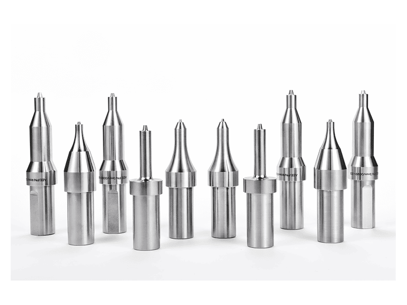
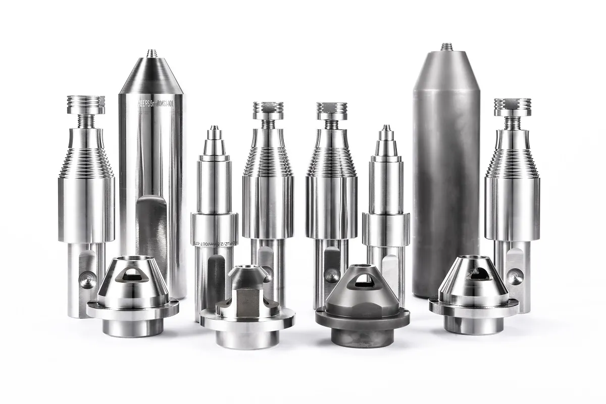
Tool condition can change the failure location between the nugget and the HAZ without any change in welding parameters. <AEE provides customer with optional features FSW tool> covers which pin and shoulder options are worth specifying when qualification data must stay repeatable across tool changes and production batches.
The most common qualification gap we see is a set of tests that passes on a machined coupon but cannot be reproduced on the production joint because the fixture, clamping, or plate flatness changed. That gap closes when the test plan is built around the production joint configuration and the actual tool design.
If your next qualification involves aluminum plates, lap or dissimilar joints, or fatigue requirements, send the part drawing, joint configuration, and target test standard to [email protected] or call +86 18325808715. We can review the specimen extraction plan, identify whether the bend and fatigue requirements fit your FSW tool and machine, and propose a qualification matrix before you cut the first coupon.
What Do Engineers Ask About FSW Joint Mechanical Testing?
Do FSW joints need different tensile specimens than fusion welds?
Not in specimen geometry, but in how the failure location is recorded. Transverse tensile specimens follow the same standard preparation as fusion welds, usually ISO 4136 or ASTM E8. The difference is that a code-compliant FSW joint may fail in the nugget, the HAZ, or the parent material, and each location means something different. A report that records only the breaking force loses the most useful piece of information. Always pair the tensile break with a macro section and note whether the failure was ductile through the parent plate or opened a root closure line.
What qualifies as a pass in FSW bend testing?
It depends on the bend direction and the location of the first crack. A surface crack starting from a poorly machined edge is not a weld failure, while a root-origin crack through a kissing bond is a genuine defect even if it appears late in the bend angle. Most qualification plans set a bend radius and a maximum crack length, but the pass criterion should also state whether cracks in the parent material or the shoulder boundary count. If that requirement is not written down, the result is open to disagreement.
Is fatigue testing mandatory for every FSW qualification?
Many teams assume fatigue testing is required because FSW appears in EV and aerospace applications. It is not automatic. Fatigue testing is included when the component carries cyclic loads and the customer specification demands an S-N curve or a proof test at a given stress ratio. Static tensile and bend data cannot substitute for a fatigue test because they do not show how a hook or root closure line grows under repeated loading. If the application is static, fatigue may be left out. If the application is a battery tray or chassis part, the customer usually sets the target cycle count.
Why do FSW lap joint specimens fail at a lower load than butt joints?
This question should be reframed as: where does the crack start in the lap joint? In an FSW lap joint, the two sheets form a hook defect at the original interface, and the loaded side determines whether that hook is pulled open or pressed closed. The weld nugget itself may be strong, but the joint stops behaving like a simple shear lap. Before ordering test material, confirm the sheet stack order and the pin geometry. Share your lap joint drawing and required load with [email protected] or +86 18325808715 and we can advise whether the hook should be positioned on the non-loaded side for your test setup.
If you’re interested, check out these related articles:
AEE attend 13th International Symposium on FSW in Kyoto, Japan on 21 – 23 May 2024
AEE provides customer with optional features FSW tool