
FSW Joint NDT: Choosing X-ray, Ultrasonic, or Phased Array
Table of Contents
- What Does an FSW Joint Defect Look Like?
- Which NDT Methods Actually Work for FSW Joints?
- Why Does X-ray Alone Miss Critical FSW Flaws?
- How Do You Combine NDT Methods Without Overspending?
- What Should You Confirm Before Finalizing Your Inspection Plan?
- What Else Do Quality Teams Ask About FSW Joint NDT?
- Is phased array always better than conventional UT for FSW joints?
- Can X-ray replace ultrasonic testing for aluminum FSW weld qualification?
- What is the difference between a kissing bond and a tunnel defect?
- How many NDT methods are required to accept an FSW joint?
FSW joint NDT fails when quality teams treat it as a single checkbox exercise. Friction stir welds produce a different defect population than fusion welds: root flaws, kissing bonds, and tight tunnels that radiography often misses, while scattered porosity from poor surface preparation is easy to overreact to. Without a method matched to the actual flaw morphology, a production line can ship weak joints or scrap good parts. This article explains which inspection methods earn their cost on FSW joints, why X-ray alone creates false confidence, and how phased array ultrasonic testing becomes the backbone of a practical inspection plan.
What Does an FSW Joint Defect Look Like?
A friction stir weld is not a cast fusion nugget. The process plasticizes material without melting it, so the defect types come from insufficient heat, insufficient forging pressure, or incorrect tool position rather than solidification cracking. The defects that matter for NDT selection are usually one of five groups.
Tunnel and wormhole defects sit in the advancing side of the stir zone. They form when travel speed is too high or rotation speed is too low, leaving an internal channel that the shoulder cannot forge shut. In 6xxx aluminum battery tray seams and water cooling plate welds, these defects can be long, intermittent, and oriented almost parallel to the weld line.
Lack of penetration and root flaws are the harder problem. A pin that is too short, a worn tool tip, or a machine that loses plunge control can leave an unjoined root face. The result is not always a visible gap. It can be a tight interface with only partial bonding. Kissing bonds occur when two surfaces meet under pressure but do not fully coalesce, which is common in high-strength 7xxx alloys and some dissimilar combinations.
Hook and cold lap defects appear in lap joints when softened material flows upward along the interface. These defects create a crack-like notch that is easy to miss from the top surface but severe under tension or fatigue loading. Surface flash, underfill, and the final exit hole are visible and should be caught early, but they are not the main risk.
In our process development work, we treat tunnel and root flaws as the two defects that drive NDT selection. Surface defects can usually be caught before scanning, but subsurface tight flaws decide whether the part passes or fails.
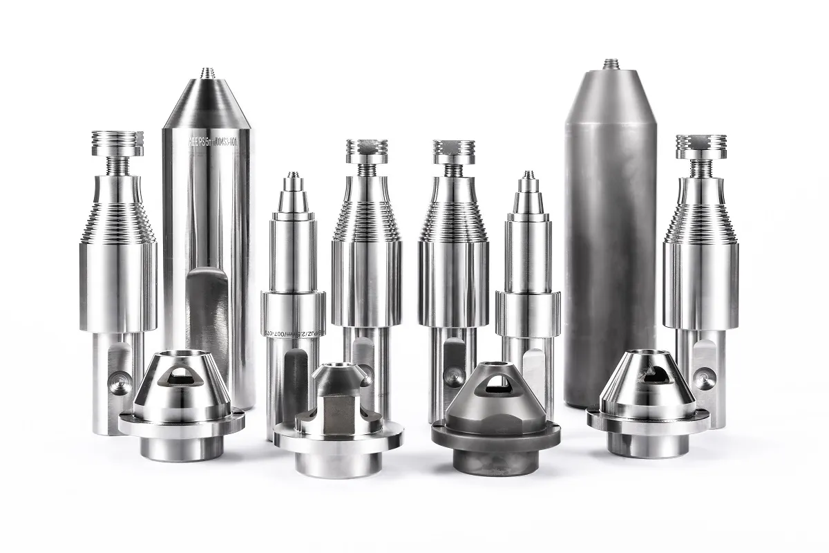
Which NDT Methods Actually Work for FSW Joints?
The method table below is a filter, not an acceptance plan. FSW joint NDT should start with the defect types that occur most often in the specific joint and alloy, not with the equipment already available in the lab.
| Method | Defect types it catches | Main limitation |
|---|---|---|
| Visual inspection | Surface flash, underfill, exit hole, gross misalignment | Misses all subsurface defects |
| Liquid penetrant | Surface-breaking hooks and cold lap cracks | Needs clean surfaces and access to both sides |
| Eddy current | Near-surface cracks and some conductivity changes | Limited depth, not reliable for root flaws in thick sections |
| X-ray radiography | Voids, large tunnels, density changes | Misses tight planar flaws and kissing bonds |
| Phased array UT | Root flaws, wormholes, lack of penetration, sidewall cracks | Requires a scan plan and reference blocks specific to FSW |
Visual inspection and penetrant testing are the cheapest first line. They catch defects that a volumetric method might not resolve because the flaw is open to the surface. Eddy current works on thin aluminum sections and can be automated, but it is not the right tool for a 10 mm or thicker root gap.
X-ray radiography is useful when the part has complex internal geometry, when the defect population includes porosity from surface contamination, or when a customer acceptance requirement specifically demands film records. Phased array ultrasonic testing is stronger for the planar and root-shaped flaws that dominate FSW joints because it controls beam angle and focal depth.
Why Does X-ray Alone Miss Critical FSW Flaws?
Radiography detects density changes. A void or tunnel changes the amount of material the X-ray beam passes through, so it shows up as a dark or light indication depending on the film or digital detector setup. That works for open volumetric defects.
FSW root flaws and kissing bonds often have no meaningful density change. Two surfaces can be pressed together tightly enough to pass a radiographic beam but still lack metallurgical bonding. In a 7xxx aluminum stiffener or a dissimilar joint, the indication can be absent while the joint fails at a fraction of the expected fatigue life.
There is a second issue. Many FSW applications are long straight seams on battery trays, rail panels, or cooling plates. Full length radiography of a 2 m seam is slow, expensive, and creates radiation exclusion zones that disrupt production. Phased array ultrasonic testing can scan the same seam from one side with encoded position data and save a permanent record for traceability.
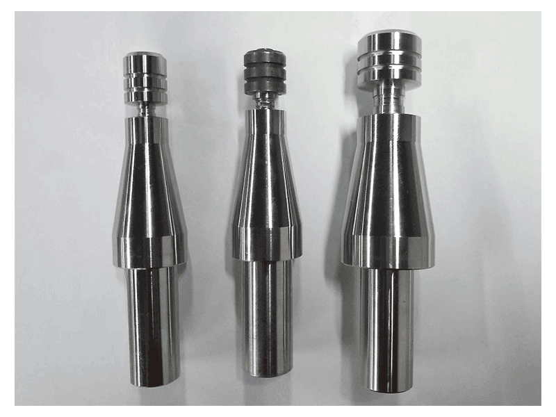
Tool wear changes the defect population before any NDT scan begins. <AEE provides customer with optional features FSW tool> covers how optional shoulder and pin configurations alter material flow, and why a fixed inspection setup may need re-qualification when the tool changes.
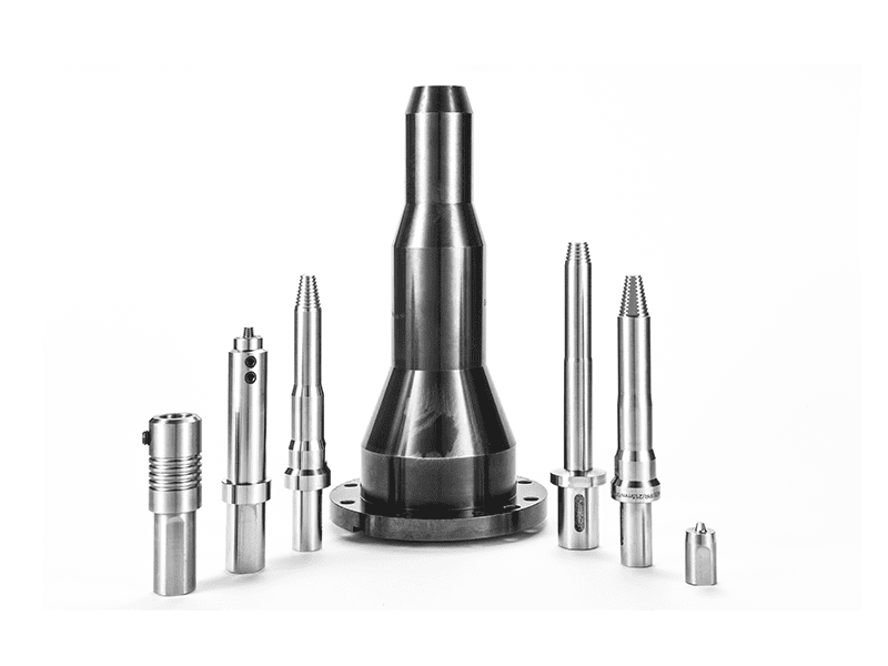
Conventional UT can inspect a straight butt weld from a single side, but it is slower to cover multiple angles. Phased array uses an array of elements to sweep a range of angles without moving the transducer as much, and it can focus at the root, the advancing side, or the retreating side. That is why we place PAUT at the center of most FSW volumetric inspection plans, with X-ray used for the specific cases radiography handles better.
How Do You Combine NDT Methods Without Overspending?
Practical FSW joint NDT combines one low cost surface method with one well chosen volumetric method. The combination depends on joint type and failure consequence. For a cosmetic part with no load path, visual and penetrant may be enough. For a sealed enclosure such as a battery tray or a liquid cooling plate, visual, PAUT, and a leak test or pressure test usually earn their cost. For lap joints with hook risk, PAUT plus a qualified penetrant step on accessible edges is stronger than X-ray alone.
The order also matters. We start with visual and dimensional checks before the part enters NDT. If a surface defect is present, it does not make sense to spend money scanning underneath it. Then PAUT scans the volume from the accessible side. X-ray enters only when porosity or dissimilar material density makes it necessary, or when the customer specification requires radiographic records.
If we can only choose one automated volumetric method, we choose phased array. It catches the tight defects that send FSW joints out under load. Radiography alone leaves a blind spot exactly where FSW is most likely to fail.
If your FSW part includes a root side hook, a lap joint with cold lap risk, or a dissimilar combination, the method selection is not a paper exercise. Send your joint drawing, alloy grade, and any existing scan data to [email protected] and we will confirm whether PAUT coverage is sufficient for your geometry.
For aluminum to copper or other dissimilar joints, the NDT picture changes again because acoustic impedance and density differ across the weld. <Customized Dissimilar Material Welding Manufacturers in China> covers why those process windows are tighter, and why reference blocks need to be made from the actual material combination before scanning.
What Should You Confirm Before Finalizing Your Inspection Plan?
Most inspection gaps come from reusing a fusion welding inspection plan on FSW joints. The defect population is different, the geometry is often a long aluminum seam, and the method that worked on a steel weld may not catch a root flaw on a 6xxx alloy battery tray.
That is the pain point. The solution is a short NDT matrix matched to your joint type, material, and failure consequence, with scan directions and acceptance criteria written for FSW flaws rather than fusion porosity.
If you are qualifying a new FSW part or reviewing an existing production line, send your part number, joint drawing, material grade, and current NDT results to [email protected] or call +86 18325808715. We will return a practical inspection sequence with the specific scan directions, reference block requirements, and acceptance thresholds your part needs. This is not a generic consulting call. It is a technical review aimed at closing the gap between what you scan and what your FSW joint can actually fail on.
What Else Do Quality Teams Ask About FSW Joint NDT?
Is phased array always better than conventional UT for FSW joints?
No. Phased array is usually better for complex profiles and lap joints, but conventional UT can handle long straight butt seams with a single optimized angle. The advantage of PAUT is not magic; it is the ability to sweep multiple angles and focus the beam at a specific depth. That makes it more likely to find a root flaw that is not aligned with a fixed transducer. Conventional UT remains useful when the joint is straight, the material is homogeneous 6xxx aluminum, and the production line needs a low cost encoded scan. For thick plates or curved parts, we move to PAUT.
Can X-ray replace ultrasonic testing for aluminum FSW weld qualification?
Some quality teams assume X-ray is the higher standard because it has been the default in fusion welding. That assumption is dangerous for FSW. Radiography detects density changes, not bond quality. A tight root flaw or kissing bond can pass a radiographic film while failing in service. X-ray should remain in the plan when porosity, internal channels, or customer film records matter, but it should not be the sole volumetric method. Ultrasonic testing, and especially phased array, gives a better view of planar FSW flaws.
What is the difference between a kissing bond and a tunnel defect?
The more useful question is which one passes a density based test. A tunnel is an open or partially open channel that displaces material, so it has a density change. A kissing bond is a tight interface where two surfaces meet but do not fully coalesce, so there may be no density change at all. Tunnels often grow from insufficient heat or excessive travel speed. Kissing bonds tend to come from insufficient forging pressure or surface contamination. Both matter, but they require different detection logic: X-ray for the tunnel, angled ultrasonic beams for the kissing bond.
How many NDT methods are required to accept an FSW joint?
In the programs we have qualified, the number is usually not the issue. One volumetric method matched to the defect type is worth more than three methods aimed at the wrong failure mode. A simple non load path part may need only visual and penetrant. A sealed battery tray or cooling plate usually needs visual, PAUT, and a leak or pressure test. The acceptance plan should be built from joint type, material, and failure consequence, not from a fixed count. Before you lock the inspection matrix, send your application data to [email protected] and we will confirm which NDT methods fit your specific acceptance criteria.
If you’re interested, check out these related articles:
AEE attend 13th International Symposium on FSW in Kyoto, Japan on 21 – 23 May 2024
AEE provides customer with optional features FSW tool