
FSW in Shipbuilding: Joining Large Aluminum Decks & Stiffened Panels
Table of Contents
- Why Shipbuilding Favors Friction Stir Welding for Aluminum Decks
- Design Requirements for Large Decks and Stiffened Panels
- Equipment Configurations for Marine Panel Welding
- Tooling Strategy for 5xxx and 6xxx Marine Alloys
- Process Control and Distortion Management
- Quality Verification for Marine Aluminum FSW Joints
- Production Layout for Large Aluminum Deck Panels
- Common Defects and Root-Cause Prevention in Marine Panels
- Specification Checklist for Shipbuilding FSW Equipment
- Get a Marine FSW Feasibility Review
- FAQ
- What aluminum alloys can FSW weld for marine decks?
- How thick can FSW weld for shipbuilding panels?
- Does FSW require backing support for stiffened panels?
- How does FSW control distortion in large decks?
- What quality standards apply to FSW in ship structures?
- Can FSW weld closed profiles and hollow extrusions used in ship decks?
- References
Friction stir welding has moved from laboratory process to production requirement in shipbuilding because aluminum decks and stiffened panels demand exactly what the method provides: a solid-state joint with low distortion, no porosity, and mechanical properties close to the parent plate. In high-speed ferries, patrol craft, workboats, and large aluminum superstructures, weight reduction is not a styling choice. It controls fuel burn, payload, and stability. Conventional fusion welding of 5xxx and 6xxx marine aluminum introduces hot cracking risk, hydrogen porosity, and enough transverse shrinkage to require heavy straightening. FSW removes most of that burden. The process was developed at TWI in 1991 [4] and is now described in dedicated ISO standards for aluminum [1][2], with classification societies publishing acceptance rules for marine structures [3].
Why Shipbuilding Favors Friction Stir Welding for Aluminum Decks
Aluminum decks in ships are commonly fabricated from 5083, 5383, 5059, or 5754 plate with 6082 or 6061 extruded stiffeners. These alloys offer good marine corrosion resistance, but fusion welding creates several recognized problems:
- Hot cracking in 6xxx extrusions when filler chemistry is not carefully controlled.
- Porosity from hydrogen gas absorbed in the molten weld pool.
- Softening in the heat-affected zone that reduces local strength.
- Angular distortion and panel waviness from uneven longitudinal and transverse shrinkage.
FSW operates below the melting point of aluminum, so it avoids solidification defects such as porosity and hot cracking. The stirred region has a fine, recrystallized grain structure, and the joint can retain a high fraction of parent metal strength when parameters are correct [5]. This does not mean FSW eliminates all distortion. It replaces pronounced angular movement with a more predictable, lower-magnitude deformation pattern that is easier to manage through clamping and weld sequencing.
For shipbuilding, the practical benefit is a flatter deck. A conventionally welded aluminum deck panel may require mechanical straightening before the superstructure is erected. A properly sequenced FSW panel with rigid fixturing and balanced heat input can meet the same flatness target with less post-weld correction.
Design Requirements for Large Decks and Stiffened Panels
Before selecting a machine, shipyards should define panel dimensions, plate-alloy combination, stiffener geometry, weld length, and acceptance class.
| Design factor | Typical shipbuilding range | FSW implication |
|---|---|---|
| Deck plate thickness | 4–20 mm | Requires matched spindle force and shoulder diameter |
| Stiffener thickness | 3–12 mm | Controls pin length and backing geometry |
| Panel width | 2.5–3.5 m | Determines gantry beam and clamping width |
| Panel length | 10–18.5 m | Sets X-axis stroke or moving-fixture layout |
| Alloy combination | 5083/6082, 5383/6061 | Drives tool material and process window |
| Flatness requirement | Commonly 2–3 mm per 1 m or class rule | Requires balanced heat input and rigid tooling |
These ranges are typical for marine aluminum panel specifications, but every project must be confirmed against the applicable classification rule and the actual fabrication drawing.
Equipment Configurations for Marine Panel Welding
Equipment selection for marine panels is driven by panel width, maximum plate thickness, the need for double-side welding, and the production rate required to keep block assembly on schedule.
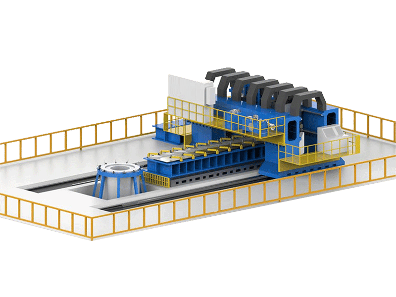
A heavy-load machine is often the baseline for shipyard work because it combines high spindle torque with high axial force. AEE’s heavy load fsw machine is a double-gantry system with a 3000 mm × 8000 mm worktable, 200 kN maximum Z-axis force, and a single-side welding depth of 100 mm in aluminum. For thick deck, bulkhead, and hull panel work, this configuration provides the force and travel envelope needed for stiff, large-area panels.
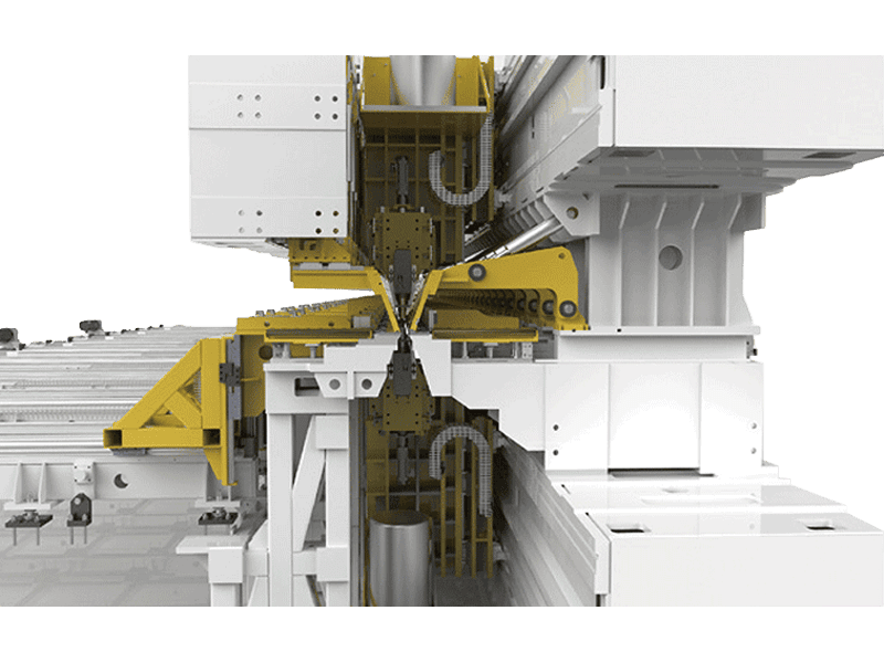
When the production task is a long, straight deck panel rather than a curved hull section, a double-head automatic line reduces handling and idle time. AEE’s fully automatic double head fsw production line handles weld thicknesses from 1.2 mm to 16 mm, maximum weld lengths of 18.5 m, and plate widths up to 3.5 m. The simultaneous double-sided welding head removes the need to flip wide panels for second-side welding, which is a decisive advantage for large stiffened panels in ship module production.
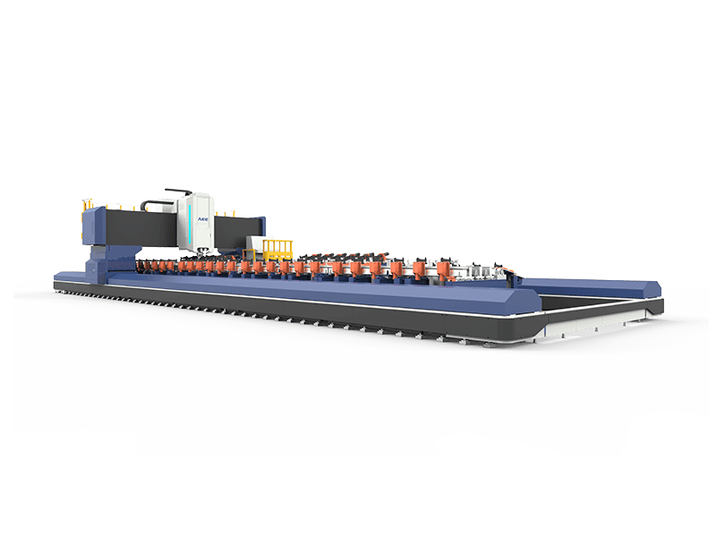
For longer profile-based components such as side shells, deck girders, and stringers, an extra-length straight profile machine can be more efficient. The extra length straight profile fsw machine provides a 16,000 mm X-axis stroke, 30 kN Z-axis force, and automatic weld-tracking functions. In shipbuilding, it supports long, straight aluminum profiles that are welded into larger structural modules before block assembly.
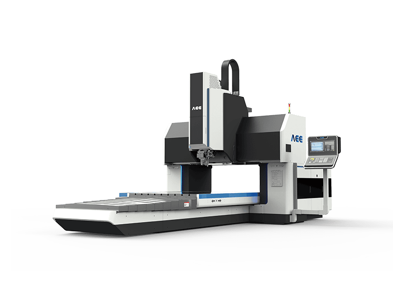
Smaller yards or those running pilot production often use a gantry fsw machine for deck panels with 2D contours and lower force requirements. AEE gantry models cover maximum welding thicknesses up to 25 mm in 1D configurations and 8 mm in 2D configurations, with welding speeds up to 5,000 mm/min for 6xxx aluminum in selected configurations.
Tooling Strategy for 5xxx and 6xxx Marine Alloys
Tool selection often determines whether a marine FSW project succeeds. 5xxx alloys are relatively forgiving because they are work-hardened rather than heat-treatable, so heat-affected-zone softening is less severe than in 6xxx alloys. However, marine deck panels usually combine 5xxx plate with 6xxx extruded stiffeners, creating a mixed-alloy joint that requires a balanced process window and careful shoulder design.
The bobbin fsw tool is frequently selected for hollow profiles and stiffened panels because it has two shoulders acting on both sides of the joint. It can reduce or eliminate the need for rigid back support, lower the risk of incomplete penetration and root defects, and make closed-profile welding practical. For workpieces in the 3.0 mm to 20.0 mm thickness range, this self-reacting tool can simplify fixture design for long straight hollow profiles and longitudinal seams in ship structures.
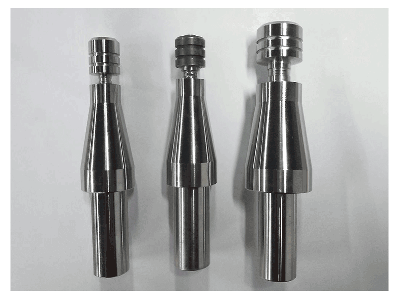
The stationary shoulder fsw tool is another relevant option for marine applications where surface finish, low heat input, and minimal thinning matter. Because the shoulder does not rotate with the pin, it applies less frictional heat to the surface, produces no flash when correctly set, and creates a more uniform thermal gradient through the plate thickness. In aluminum, stationary shoulder tooling is available for thicknesses from 1.0 mm to 110 mm, making it suitable for both thin deck overlays and heavy integrally stiffened panels.
Shipyards seldom solve deck panel distortion with a single standard tool geometry. Pin features, shoulder profiles, and retractable-pin options often require adjustment for each stiffener dimension and alloy combination. <AEE provides customer with optional features FSW tool> covers how optional tool features are matched to specific production requirements.
Process Control and Distortion Management
Distortion control in marine FSW starts before the weld begins. The panel is pressed against a rigid backing or clamping bed, and the welding sequence is arranged so that shrinkage is balanced from the center outward or in alternating passes. FSW does not use filler metal, so transverse contraction is generally smaller and more uniform than in fusion welding. At the same time, the tool’s high axial force, often 30 kN to 200 kN depending on plate thickness, demands a fixture far more rigid than a typical welding table.
Process parameters for marine 5xxx and 6xxx aluminum require careful integration of spindle speed, travel speed, tool tilt, and plunge depth. The goal is to generate enough heat to plasticize the material without exceeding the temperature window that causes excessive softening or surface defects. Robust parameter sets are developed on weld coupons and then verified on full-width panel samples. Because FSW generates significant axial force, the relationship between spindle torque, weld speed, and machine frame stiffness is central to repeatable quality.
Planning a ship deck panel production line? Send panel width, plate thickness, alloy specification, stiffener type, and target weld length to [email protected] or call +86 18325808715 for a technical review. AEE engineers can help define the machine envelope, fixture strategy, tooling package, and process window before capital equipment is committed.
Quality Verification for Marine Aluminum FSW Joints
Marine aluminum FSW joints must satisfy both production weld quality requirements and surveyor acceptance expectations. The applicable ISO standards for friction stir welding of aluminum define process qualification, workmanship, and inspection requirements [1][2]. Classification societies such as DNV publish welding rules for ship structures that include acceptance criteria. Shipyards should verify the specific class society and edition before qualification [3].
In practice, quality verification for deck panels usually includes:
- Visual inspection for surface flash, undercut, and exit-hole condition.
- Radiographic or ultrasonic testing for root flaws and incomplete penetration.
- Phased array ultrasonic testing for improved resolution in thick plate.
- Bend tests, tensile tests, and macro-sections for procedure qualification.
- Dimensional inspection of flatness and weld position after cooling.
FSW joints produce a fine, recrystallized weld nugget and avoid many solidification defects that complicate ultrasonic interpretation. Inspectors still need approved scanning techniques and procedure references for class approval [1][2][5]. Early coordination with the classification society and the machine supplier reduces later rework.
Production Layout for Large Aluminum Deck Panels
A shipyard produces more than a weld seam. It must manage material flow, panel turnover, and fixture changeover. For a deck panel line, a typical sequence is:
- Plate and stiffener pre-machining.
- Panel lay-up and clamping.
- First-side FSW.
- Panel turnover or automatic double-head second-side welding.
- Inspection and dimensional release.
- Transfer to subassembly or block assembly.
A double-head machine removes the turnover step and allows both sides of a wide panel to be welded in one fixture setup. For long panels, this reduces crane handling and the risk of introducing distortion between passes. Automated loading, clamping, laser tracking, and process data logging support repeatable quality in series production rather than prototype-level manual control.
Common Defects and Root-Cause Prevention in Marine Panels
Marine aluminum FSW challenges usually center on incomplete penetration, root flaws in lap joints, and surface flash. In stiffened panel welding, incomplete penetration is often caused by insufficient pin length, excessive travel speed, or inadequate axial force. Root flaws in lap configurations may appear as hooking or cold lap because the interface does not fully consolidate. These defects are reduced by correct tool profile, plunge depth control, and an optimized overlap width.
Surface flash often indicates excess heat input, too much shoulder plunge, or a soft fixture that allows material to escape ahead of the tool. A stationary shoulder tool reduces flash because the non-rotating shoulder maintains downward pressure without adding rotational friction to the crown surface. Bottom-side flash is usually controlled with backing support, bobbin tooling, or tighter clamping. Spindle torque and axial force should be monitored continuously because both respond earlier than visual defects.
Specification Checklist for Shipbuilding FSW Equipment
When evaluating FSW machines for marine deck and stiffened-panel production, shipyards should confirm:
- Maximum single-side and double-side welding depth for the target alloys.
- Work envelope, including X-axis travel, gantry width, and Z-axis force.
- Spindle torque, speed range, and tool holder interface.
- Clamping and backing systems for panel flatness.
- Automatic weld tracking, force control, and process data recording.
- Compliance with CE, ISO 9001, and any shipyard-specific safety requirements.
AEE’s marine-relevant systems include the heavy-load double gantry machine with 100 mm single-side aluminum depth, the fully automatic double-head line for panels up to 18.5 m by 3.5 m, and the extra-length straight profile machine for long structural profiles. These systems are supported by pin tools, standard tool holders, and customized tooling packages.
For shipyards importing equipment or working with Chinese FSW manufacturers, the main differentiator is how the supplier handles non-standard requirements such as mixed 5xxx/6xxx panels, closed profiles, or special inspection classes. <Customized Dissimilar Material Welding Manufacturers in China> covers how co-engineering and process adaptation reduce implementation risk.
Get a Marine FSW Feasibility Review
If you are planning aluminum deck or stiffened-panel production for shipbuilding, send panel dimensions, plate and stiffener alloys, thickness, weld length, and the classification society to [email protected] or call +86 18325808715. Aerospace Engineering Equipment (Suzhou) Co., Ltd. will review the application, propose a machine and tooling configuration, and support welding trials before delivery.
FAQ
What aluminum alloys can FSW weld for marine decks?
FSW is suitable for 5xxx plate alloys such as 5083, 5383, 5059, and 5754, and for 6xxx extruded stiffeners such as 6082 and 6061. It can also weld mixed 5xxx-to-6xxx panels when the process window is qualified for the specific combination. Marine-grade alloys are selected for corrosion resistance and strength, and FSW preserves these properties more effectively than fusion welding because it avoids solidification defects.
How thick can FSW weld for shipbuilding panels?
For production marine panels, deck plate thicknesses commonly range from about 4 mm to 16 mm. For heavy integrally stiffened panels and hull sections, heavy-load FSW machines can weld single-side aluminum thickness up to 100 mm and double-side up to 190 mm. The machine force, spindle torque, and tool design must be matched to the actual plate thickness and alloy.
Does FSW require backing support for stiffened panels?
Conventional FSW usually requires a rigid back support or backing bar to react the axial forging force. Bobbin or self-reacting tooling can eliminate the need for rigid rear-side support because it uses two shoulders that act on both sides of the joint. This is useful for closed profiles and hollow extrusions where access to the back side is limited.
How does FSW control distortion in large decks?
FSW operates below the melting temperature of aluminum and does not use filler metal, so shrinkage is lower and more uniform than in fusion welding. Distortion is further controlled by rigid clamping, a suitable weld sequence, balanced heat input between passes, and double-side welding where practical. The result is a flatter panel with less post-weld straightening.
What quality standards apply to FSW in ship structures?
Aluminum FSW is covered by ISO 25239 for procedure specification, qualification, and inspection requirements. Classification society rules, such as those published by DNV for ship materials and welding, provide additional acceptance frameworks. Shipyards should confirm the applicable edition with the class society before qualification.
Can FSW weld closed profiles and hollow extrusions used in ship decks?
Yes. Bobbin-type FSW tooling allows closed profiles and hollow sections to be welded without full rear-side access. It supports thicknesses from 3.0 mm to 20.0 mm in common aluminum alloys and is applied to long straight hollow profiles and longitudinal seams in transportation and marine structures.
References
[1] ISO 25239-4:2020, Friction stir welding — Aluminium — Part 4: Specification and qualification of welding procedures, International Organization for Standardization, 2020.
[2] ISO 25239-5:2020, Friction stir welding — Aluminium — Part 5: Quality and inspection requirements, International Organization for Standardization, 2020.
[3] DNV, Rules for Classification: Ships — Part 2 Materials and Welding — Chapter 3 Welding, DNV AS, current edition.
[4] W. M. Thomas et al., “Friction Stir Butt Welding,” International Patent Application No. PCT/GB92/02203, 1991.
[5] R. S. Mishra and Z. Y. Ma, “Friction stir welding and processing,” Materials Science and Engineering: R: Reports, vol. 50, no. 1–2, pp. 1–78, 2005.
If you’re interested, check out these related articles:
AEE attend 13th International Symposium on FSW in Kyoto, Japan on 21 – 23 May 2024
Refill Friction Stir Spot Welding (RFSSW)
AEE provides customer with optional features FSW tool
Customized Dissimilar Material Welding Manufacturers in China