
FSW in Rail Transit: Body Panels, Floors, and Traction Beams
Table of Contents
- Why FSW Suits Rail Transit Aluminum Structures
- Train Body Panels: Extra-Long Profile Welding
- Floors and Underframe Components: Hollow Sections and Load Paths
- Process Control and Quality Verification for Rail Welds
- Equipment Planning and Production Economics
- Start with a Feasibility Weld, Not a Guess
- Common Questions About Rail Transit FSW
- What aluminium alloys are commonly FSW-welded in rail body panels?
- Can FSW weld hollow aluminium extrusions without backing support?
- How are FSW weld quality and leak-tightness verified in rail production?
- What is the difference between EN 15085 and ISO 25239 for rail FSW?
- What production volume is required to justify an automated FSW line?
- References
Friction stir welding (FSW) has become a production-critical joining process for aluminium rail structures because it addresses the central challenge of joining long, thin-walled profiles with repeatable dimensions and low distortion. Dedicated international standards now define process qualification and inspection for aluminium FSW [1]. In rail transit, body sidewalls, roof panels, floor assemblies, and underframe traction beams increasingly use FSW where long straight welds, tight dimensional requirements, and repetitive production cycles make fusion welding less attractive.
Why FSW Suits Rail Transit Aluminum Structures
EN 15085, the railway welding standard, sets requirements for welding railway vehicles and components, including design, qualification, and quality levels [2]. FSW fits this structure well because it is a machine-led process with digital parameter logging, consistent heat input, and no filler metal or shielding gas. Compared with MIG/TIG fusion welding of 6xxx-series aluminium extrusions, FSW typically produces lower heat input, reduced distortion, and avoids solidification porosity. These properties are documented in the aluminium FSW literature [3].
For rail body panels, the practical benefits are dimensional stability, good surface appearance, and the ability to produce long continuous welds without the stop-start discontinuities common in manual or semi-automatic fusion welding. The low thermal distortion is especially important when joining wide multi-cavity extrusions that must remain flat for assembly and aerodynamic performance.
Early feasibility work is the fastest way to validate a rail FSW application before committing to production equipment. If you have a profile drawing or a short sample section, contact [email protected] for an initial process review and tooling recommendation.
Train Body Panels: Extra-Long Profile Welding
Rail carbody sidewalls and roof panels are typically assembled from multiple hollow aluminium extrusions, with weld lengths reaching 10 m to 20 m or more. This places strict demands on machine travel, bed rigidity, clamping accuracy, and seam tracking. The process was first demonstrated at TWI in 1991 and has since been industrialized for long-profile aluminium welding [4].
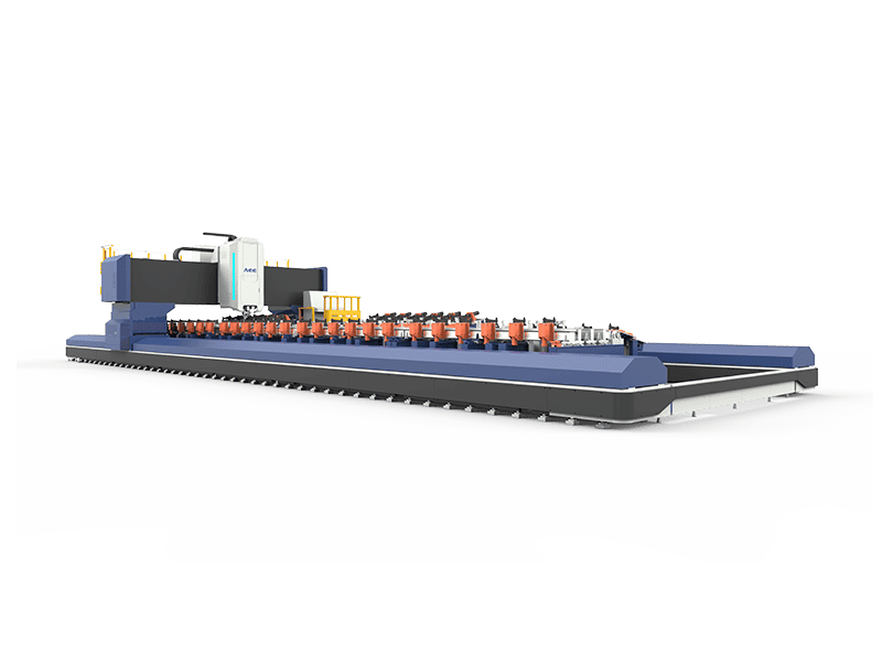
A dedicated extra-length straight profile FSW machine can handle these long runs. For example, AEE’s extra-length straight profile FSW machine provides an X-axis stroke of 16,000 mm, Y-axis stroke of 4,000 mm, positioning accuracy of 0.03 mm, and repeatability of 0.03 mm. It is designed for 1D linear welding of rail transit body structural parts and supports optional constant pressure control, laser weld tracking, start-point tool setting, and welding parameter acquisition.
For high-volume rail profiles, an automated line may be more appropriate. AEE’s fully automatic double-head FSW production line supports weld thickness from 1.2 mm to 16 mm, maximum weld length up to 18,000 mm, and maximum plate width up to 3,500 mm. It combines double-sided welding, automatic loading and clamping, laser tracking, weld inspection before welding, material discharge, and cutting in a single integrated process.
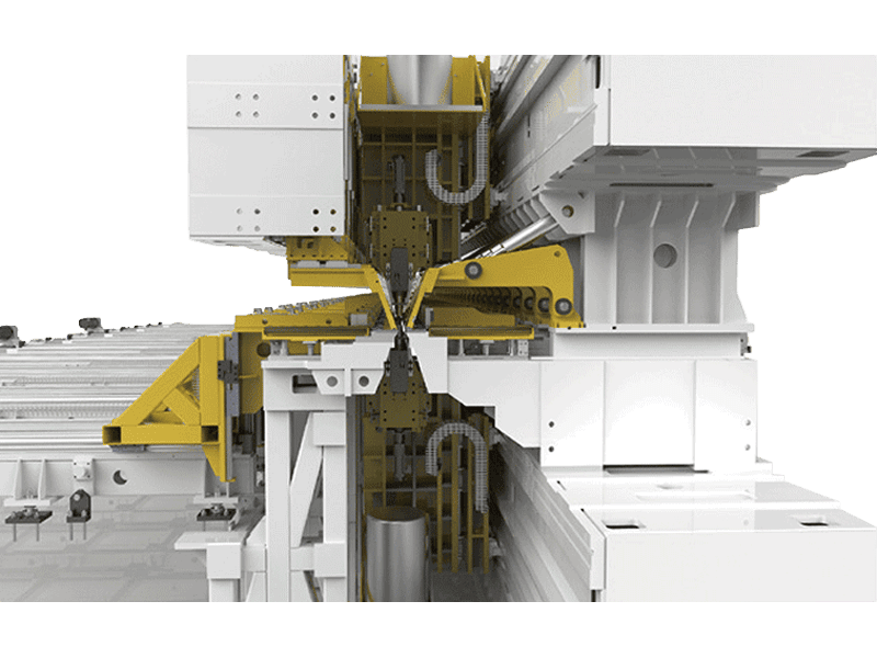
These systems are built for long straight profile welding in rail transit and shipbuilding. The key process requirement is not just weld travel length but consistent clamping force and thermal management over the full seam. Uneven clamping can produce local gaps, while uncontrolled heat input can soften precipitation-hardened 6xxx alloys and reduce post-weld strength.
Floors and Underframe Components: Hollow Sections and Load Paths
Floor panels and underframe structures present a different challenge: they combine flat panel welding with local load-bearing features such as traction beams, bolsters, and cross-members. Many floor panels are multi-cavity extrusions that require either single-sided FSW with rigid backing or self-reacting tools when back support is impossible.
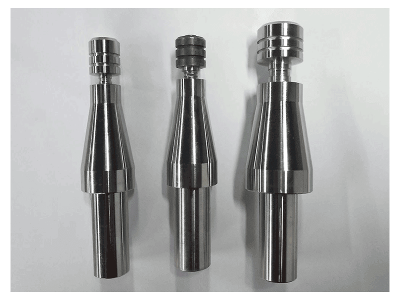
The bobbin FSW tool is useful in these applications. AEE’s bobbin FSW tool welds common 4xxx, 5xxx, and 6xxx aluminium alloys in thicknesses from 3.0 mm to 20.0 mm. It uses dual shoulders on the top and bottom of the workpiece, which eliminates the need for rigid back support and helps prevent root lack-of-penetration. This makes it suitable for hollow profiles, long straight hollow sections, and rail transit components.
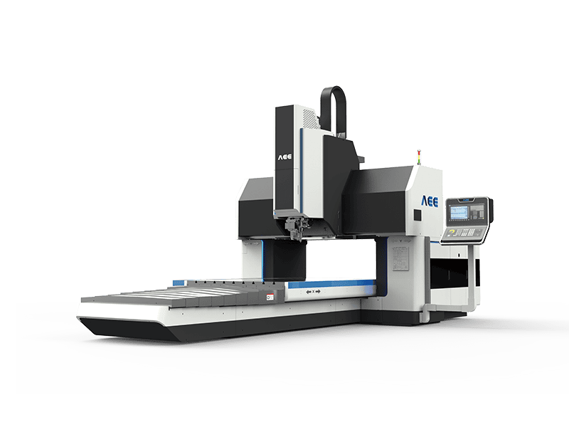
For floor panels and traction beams with curved or 2D weld paths, a gantry FSW machine offers a large worktable, adjustable table height, and 2D servo control for constant welding angle. The gantry line includes models with welding thickness up to 25 mm and X-axis strokes up to 4,000 mm, depending on configuration. Product data from AEE indicates that these machines can achieve stable welding of 1D and 2D curved welds with positioning accuracy of 0.05 mm and repeatability of 0.03 mm for selected models.
Traction beams and underframe members often use thicker 6xxx-series profiles, in the range of 8 mm to 16 mm. Designers should specify the required penetration depth, joint configuration, and load direction before selecting a machine. A common mistake is to treat all rail aluminium parts as thin sheet; underframe structural members may require higher spindle torque and Z-axis force than body panel welds.
The most useful input for a rail FSW assessment is a machined profile sample or a 2D cross-section drawing. Send your section drawing, alloy grade, target weld length, and annual volume to [email protected] for a preliminary machine and tooling recommendation.
Process Control and Quality Verification for Rail Welds
Rail FSW procedures should be qualified to the relevant application standard. ISO 25239 covers aluminium FSW and provides a framework for welding procedure qualification and inspection [1]. In rail projects, this is typically read together with EN 15085 requirements for welding manufacturers [2]. The overlap means a rail FSW supplier should be able to provide documented WPS records, operator training, and inspection data rather than only sample welds.
Common quality checks include visual examination, penetrant testing, radiographic or ultrasonic inspection, and tensile or bend testing on qualification coupons. For aluminium FSW, ultrasonic phased array is often used to detect root flaws, internal voids, or incomplete penetration. The welded joint must also be evaluated for hooking and cold lap in lap configurations, while tunnel defects, voids, and flash can occur when tool geometry or travel speed is outside the process window. These defect mechanisms are well documented in the FSW literature [3].
Retractable pin tools are frequently specified for rail applications where closed-contour welds must avoid exit holes. AEE’s retractable FSW tool allows the pin to be withdrawn into the shoulder as welding approaches completion, filling the exit hole and producing a sealed joint. This is useful for cylindrical, circumferential, and closed-loop rail components such as equipment housings and end frames.
Rail welding procedures also evolve through shared research and symposium-level technical exchange. <AEE attend 13th International Symposium on FSW in Kyoto, Japan on 21 – 23 May 2024> covers AEE’s participation in that international technical programme.
Rail programmes rarely run on a single standard machine configuration; optional tooling, laser tracking, and force/position feedback are commonly specified for long-run and closed-loop work. <AEE provides customer with optional features FSW tool> covers the optional tool and control packages that support these production decisions.
Equipment Planning and Production Economics
The table below maps common rail applications to the most relevant FSW platform and tool selection.
| Rail component | Typical weld form | Common thickness | Preferred machine/tool | Main FSW advantage |
|---|---|---|---|---|
| Body sidewall / roof panel | Butt | 4–8 mm | Extra-length machine or automatic double-head line | Long straight welds, low distortion |
| Floor deck panel | Butt/lap | 3–10 mm | Gantry machine or automatic double-head line | Flatness, no porosity |
| Hollow profile section | Butt/circumferential | 3–20 mm | Bobbin FSW tool | No back support required, root defect control |
| Traction beam / bolster | Butt/T-joint | 8–16 mm | Gantry machine or heavy-load machine | Controlled penetration, high load |
These recommendations are starting points, not fixed rules. The final machine configuration depends on profile geometry, alloy temper, weld length, throughput target, and available fixture budget. Product-specific capacity should be validated with coupon tests before ordering.
For high-mix production, a modular gantry FSW machine may cover both floor panels and traction beams. For very long body panels, the extra-length straight profile FSW machine is a more focused option. For fully automated, high-volume long-profile welding, the fully automatic double-head FSW production line provides integrated loading, welding, and cutting.
Start with a Feasibility Weld, Not a Guess
Rail FSW projects share a common pattern: the weld itself is often not the highest technical risk; the failure points are fixture design, thermal management, and profile tolerance. That is why feasibility welding on the actual profile is the most reliable way to reduce risk before equipment ordering.
Send your rail component drawing, alloy grade, target weld length, and annual volume to [email protected]. The engineering team can recommend the right machine platform, pin tool, fixture concept, and process window before any equipment commitment. For direct technical inquiries, call +86 18325808715.
Common Questions About Rail Transit FSW
What aluminium alloys are commonly FSW-welded in rail body panels?
The most common rail alloys are 6xxx-series extrusions such as 6005A, 6060, and 6082. These alloys are readily extrudable, corrosion resistant, and well suited to FSW. The process can also weld 5xxx sheet and selected 7xxx high-strength alloys when the application requires higher strength, though tool wear and process windows change accordingly.
Can FSW weld hollow aluminium extrusions without backing support?
Yes. Self-reacting bobbin tools weld through the top and bottom surfaces simultaneously, so no rigid back support is required on the reverse side. This is especially useful for hollow profiles and closed sections, where conventional single-shoulder FSW would need internal support that may be difficult to install and remove.
How are FSW weld quality and leak-tightness verified in rail production?
For structural welds, visual inspection, penetrant testing, ultrasonic phased array, and radiographic testing are common. For sealed enclosures or liquid-carrying components, leak testing is added. Qualification welds are also subjected to tensile, bend, and macro-section examination to confirm penetration and nugget quality.
What is the difference between EN 15085 and ISO 25239 for rail FSW?
EN 15085 is the railway-specific welding series covering design, manufacturing, and inspection requirements for rail vehicles and components [2]. ISO 25239 addresses aluminium FSW specifically, including terminology, process specification, qualification, and inspection [1]. Rail projects commonly apply both: EN 15085 for the railway quality framework and ISO 25239 for the FSW-specific procedure.
What production volume is required to justify an automated FSW line?
There is no universal minimum volume, but automated double-head lines are usually justified when rail panel welding volume is repetitive enough to use the machine for long, straight profile assemblies. Lower-volume or high-mix work may be better served by a gantry or extra-length machine with manual loading and changeover. The breakeven depends on labour, cycle time, scrap reduction, and whether secondary operations such as cutting and inspection can be integrated.
References
[1] ISO 25239, Friction stir welding — Aluminium. International Organization for Standardization, Geneva, Switzerland, 2020.
[2] EN 15085, Railway applications — Welding of railway vehicles and components. European Committee for Standardization, Brussels, Belgium, 2022.
[3] P. L. Threadgill, A. J. Leonard, H. R. Shercliff, and P. J. Withers, “Friction stir welding of aluminium alloys,” International Materials Reviews, vol. 54, no. 2, pp. 49–93, 2009.
[4] W. M. Thomas, E. D. Nicholas, J. C. Needham, M. G. Murch, P. Temple-Smith, and C. J. Dawes, “Friction stir butt welding,” International Patent Application PCT/GB92/02203, 1991.
If you’re interested, check out these related articles:
AEE attend 13th International Symposium on FSW in Kyoto, Japan on 21 – 23 May 2024
AEE provides customer with optional features FSW tool