
FSW for Satellite Panels: Space-Grade Aluminum Joining
Table of Contents
- Why FSW Fits Satellite Panel Fabrication
- Material and Joint Design for Space-Grade Aluminum
- Tooling and Machine Requirements
- Process Control, Inspection, and Qualification
- From Coupon to Flight-Quality Panel
- Engineering Review for Satellite Panel Programs
- Frequently Asked Questions
- Is FSW strong enough for satellite structural panels?
- Does FSW leave an exit hole on the panel?
- Which aluminum alloys are most used for satellite panel FSW?
- What inspection methods are required for flight hardware?
- Can FSW handle thin panels without burn-through or excessive distortion?
- References
Satellite panels sit at one of the most demanding intersections in manufacturing: the structure must be light enough to justify every kilogram of launch mass, stiff enough to protect instruments during vibration and acoustic loading, and dimensionally stable enough to hold alignment through thermal cycling. Fusion welding introduces precisely the risks that satellite programs try hardest to avoid — porosity, hot cracking, excessive distortion, and unpredictable residual stress.
Friction stir welding (FSW) changes that calculation. The process joins aluminum without melting it. A rotating, non-consumable tool generates frictional heat, plasticizes the material locally, and forges a solid-state joint as it traverses the seam. FSW was first demonstrated in the early 1990s [1], and it has since become a production process for aerospace structures where fusion welds are either unacceptable or require extensive rework [2].
This article explains what matters for satellite panel FSW: alloy selection, joint design, tooling, machine requirements, process qualification, inspection, and the transition from feasibility coupon to flight-quality production panel.
Why FSW Fits Satellite Panel Fabrication
Satellite panels are usually machined aluminum plates, integrally stiffened panels, or framed skins. The manufacturing issue is not simply “can the seam carry load.” It is whether the panel retains its certified geometry after welding.
FSW offers three practical advantages for these structures. First, it avoids solidification defects. Because the joint forms below the melting point, there is no molten pool, no solidification cracking, and no gross porosity from dissolved gas or trapped shielding gas. Second, it reduces distortion. The peak temperature is lower and the heat input is more localized than fusion welding, so a well-fixtured panel typically comes off the tool with less out-of-plane springback. Third, the process is repeatable. Once spindle speed, travel speed, axial force, tilt, and thermal boundary conditions are locked, the result is a controlled thermal-mechanical cycle rather than an operator-dependent arc.
Those benefits are not automatic. Satellite panel FSW still requires rigid fixturing, careful backing support, and qualified parameters for the specific alloy and thickness. The acceptance standard is what separates a laboratory-quality bead from a flight-quality structural joint.
| Panel requirement | Fusion-welding risk | FSW response |
|---|---|---|
| Low porosity | Trapped gas, hot cracks | Solid-state joint with no melt pool |
| Dimensional stability | High heat input, asymmetric shrinkage | Localized heat input, lower distortion |
| Repeatable quality | Operator and shielding variability | Machine-controlled force, speed, and position |
| Fine surface finish | Weld reinforcement, spatter | Smooth crown, minimal flash when tool is correct |
| Thin-wall integrity | Burn-through, thinning | Lower peak temperature, controlled penetration |
For satellite work, the value proposition is not that FSW replaces every joint. It is that FSW removes welding from the list of unknowns that must be controlled by inspection alone.
Material and Joint Design for Space-Grade Aluminum
The most common satellite panel alloys are the same workhorse grades used elsewhere in aerospace: 6061-T6 for moderate strength and good machinability, 7075-T73 or 7075-T7351 for higher specific strength, and selected 2xxx alloys where damage tolerance and fatigue resistance dominate. The key difference is that FSW allows these alloys to be joined without introducing the solidification crack sensitivity that makes 7075 and many 2xxx grades difficult to fusion weld [2][3].
In practice, the alloy choice drives three process decisions: allowable spindle speed, required axial force, and tool material. 6xxx alloys are the most forgiving. 7xxx alloys demand higher forces and more careful thermal control to avoid excessive heat-affected zone softening. 2xxx aerospace alloys require conservative travel speeds and, in many cases, process verification at coupon level before any panel-level program is committed.
Joint design for satellite panels is usually driven by the structural load path. Common configurations include:
- Butt joints for coplanar skin panels and machined plate splices. These are the easiest to fixture and the most common production case.
- Lap joints where a skin is attached to a stringer, edge member, or doubler. Lap FSW works, but the engineer must manage interface cleanliness, clamping, and the possibility of hooking or cold-lap defects at the joint interface.
- T-joints and corner joints for assembled panel frames. These require more complex tool access, stronger fixtures, and a machine with enough stiffness in the lateral axes.
For butt joints, edge preparation is simpler than fusion welding. Mill-scale, anodizing, and light oxidation are less critical than in MIG or laser welding because the rotating tool deforms and disperses the surface oxide into the joint. That said, heavy contamination, machining coolant residue, and inconsistent gaps must still be controlled. Gap tolerance is not zero; a well-designed fixture holds the abutting edges within the gap tolerance developed during procedure qualification [3].
The strongest process rule is to qualify the joint exactly as it will fly. A tensile test performed on simple butt coupons does not automatically qualify a panel with thickness transitions, edge members, or access pockets. Qualification must represent the production configuration.
Tooling and Machine Requirements
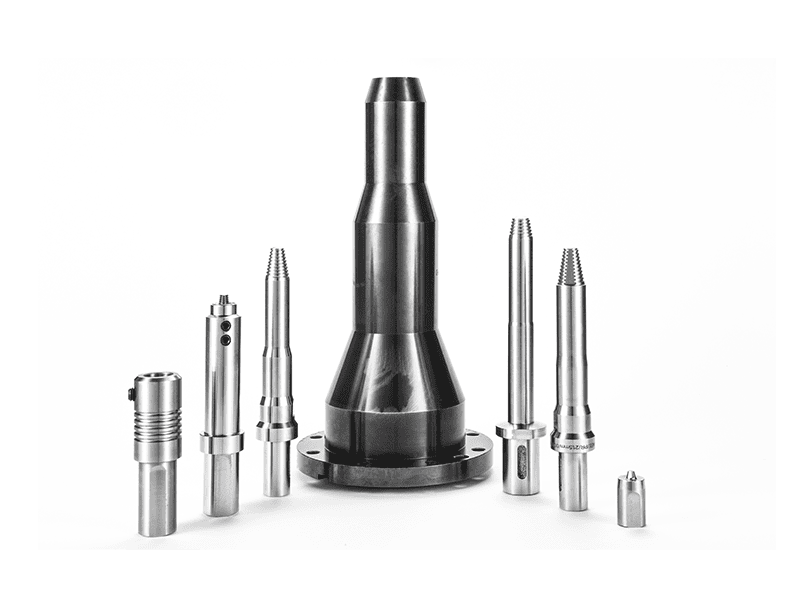
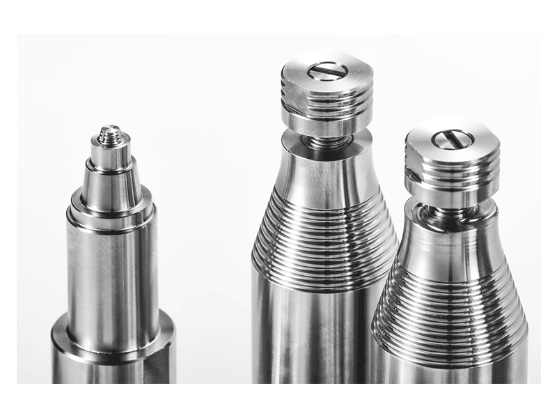
Tooling is the heart of a satellite panel FSW cell. The tool material, shoulder geometry, and pin profile determine heat generation, material flow, and surface finish.
A conventional threaded tapered pin with a concave shoulder remains the default for many flat-panel butt welds. It is simple, robust, and well understood across the industry. For production panels with closed seams or no acceptable exit hole, a retractable pin tool is the stronger choice because it fills the keyhole as the pin withdraws.
For thin satellite skins, a stationary shoulder tool reduces total heat input and improves surface appearance because only the pin rotates while the shoulder slides across the surface. For hollow or unsupported sections, a bobbin tool welds from both sides with one pass and removes the need for a rigid backing plate on the reverse face.
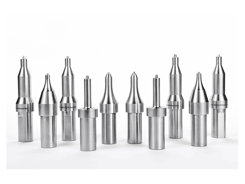
The selection should follow the joint, not the other way around. A simple butt splice on a 4 mm 6061 skin is a different tooling problem than an edge-sealed 2 mm pocket panel or a curved 3D antenna structure.
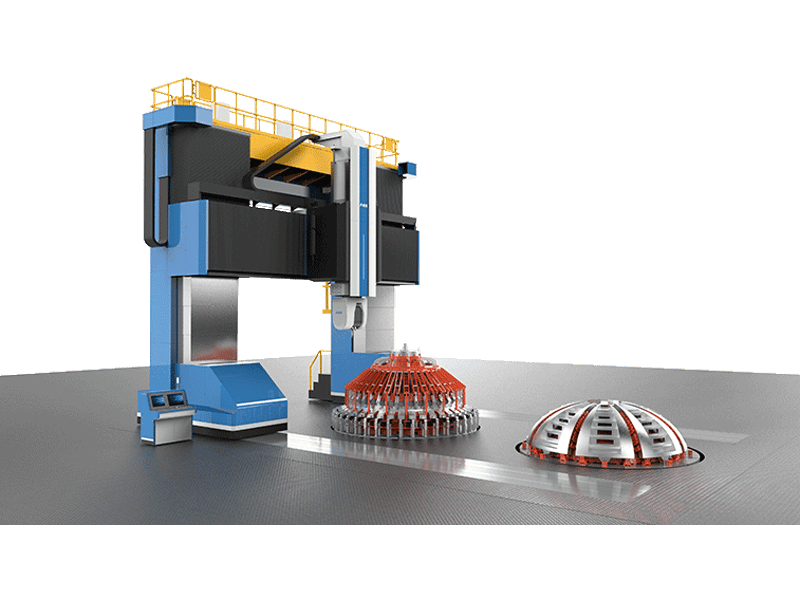
Machine selection follows the same logic. For flat single-piece panels, a gantry FSW machine with stable worktable fixturing and 2D path control is the production workhorse. A machine with sufficient Z-axis force and a stiff gantry maintains the forge condition across a full-size satellite panel without losing depth control at the center of the table.
For thick integrally stiffened panels or structural plates, a heavy-load machine with high spindle torque and high Z-axis force is required. The process is force-limited before it is speed-limited when panel thickness increases.
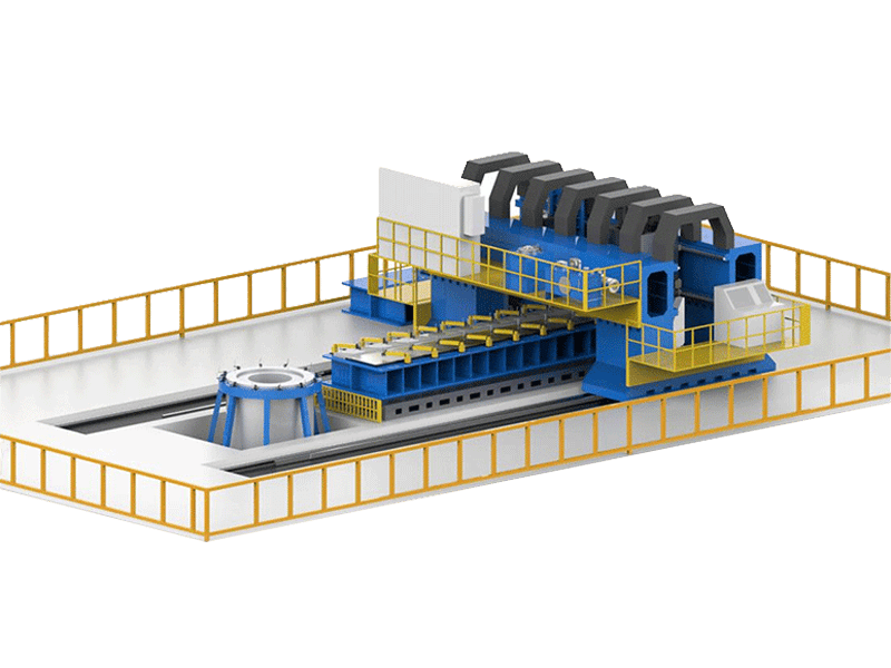
For curved structures, complex seams, or panels with non-planar joints, a 3D FSW machine with AC-head capability keeps the tool orientation normal to the weld path. That matters on satellite structure because a few degrees of shoulder misalignment changes heat input, flash formation, and joint quality.
Tool selection should not be a default to the cheapest conventional pin. <AEE provides customer with optional features FSW tool> covers how tool features such as retraction, shoulder configuration, and optional geometry affect weld access, exit-hole management, and machine utilization on production work.
The fixture is equally important. Satellite panels are thin relative to their clamping area, so fixture rigidity controls both joint alignment and thermal distortion. Backing plates should be continuous, thermally conductive, and aligned with the seam. Hard stops, side clamping, and vacuum assist are often combined to hold panel edges without creating localized bending. Thermal management is part of the fixture design, not an afterthought: the backing plate is a heat sink, and its conductivity changes the cooling rate after the tool passes.
Process Control, Inspection, and Qualification
Satellite hardware does not leave Earth on the strength of a good cross-section. It flies on evidence.
A welding procedure specification is the first formal step. The WPS must define tool geometry, tool material, spindle speed, travel speed, axial force or plunge depth, tilt angle, start and end conditions, fixture temperature, and acceptance limits. ISO 25239-4 provides a structured framework for friction stir welding procedure specification and qualification for aluminum [3]. Aerospace programs often supplement that with the requirements of AWS D17.3 or the relevant ECSS welding standard [4][5].
Qualification begins with destructive testing: tensile specimens across the joint, bend tests, macro- and micro-examination, and, where required, fatigue or stress-corrosion testing. The microstructural zones — nugget, thermo-mechanically affected zone, and heat-affected zone — are examined for defects, excessive grain growth, and abnormal flow patterns.
Non-destructive testing then verifies the production condition:
| NDT method | Primary detection | Satellite panel application |
|---|---|---|
| Visual inspection | Surface cracks, flash, underfill, keyhole condition | All seams before and after machining |
| Radiography or computed tomography | Voids, tunnel defects, embedded lack of fill | High-value panels, complex geometry |
| Phased-array ultrasonic testing | Subsurface flaws, lack of fusion, root defects | Production panels where full radiography is too slow |
| Dye penetrant | Surface-breaking defects | Machined or secondary-finished welds |
| Leak test | Through-wall leakage | Sealed enclosures, pressurized panels, thermal hardware |
The right inspection set depends on the acceptance class and program risk. A non-structural cover panel may require visual plus limited ultrasonic coverage. A primary load path or sealed propulsion-related panel may require full volumetric inspection and leak testing.
Process monitoring closes the loop. Recording spindle torque, axial force, X/Y/Z position, and temperature on every panel creates a traceable record that separates a qualified seam from an unqualified one. Modern machines can log force and torque at high frequency; that data is valuable when a later anomaly must be evaluated. It is not a substitute for destructive qualification, but it reduces the amount of destructive testing needed on production hardware.
From Coupon to Flight-Quality Panel
The safe route to satellite panel FSW is not to buy a machine and immediately weld flight panels. It is to begin with material-specific coupons, develop the process window, then move to panel-level demonstrators.
Coupon trials should vary spindle speed, travel speed, force, and tool geometry until the joint consistently meets the tensile, bend, and defect limits required by the program. The result is a parameter window, not a single recipe. A window is necessary because production panels differ from small coupons in thermal mass, clamping stiffness, and weld length.
Once the window is established, the next step is a representative panel trial. The panel should include the same alloy, thickness, joint type, edge conditions, and fixture strategy as the flight configuration. It should be inspected with the full production NDT set, then sectioned for destructive validation at critical locations.
Take a practical shortcut on this decision path: if you can define the joint geometry, alloy, thickness, acceptance class, and annual panel volume, a tooling engineer can narrow the candidate machine and tool set to a small number of proven combinations. Send the drawing package and target throughput to [email protected] and request sample welding before committing to a full capital purchase. That one step usually exposes whether the main risk is tool life, distortion, or machine capability — and it does so before the production line exists.
Coupon-level parameter studies are the first real proof that a chosen tool–alloy combination can meet satellite panel acceptance limits. <AEE attend 13th International Symposium on FSW in Kyoto, Japan on 21 – 23 May 2024> covers the international process questions and tooling trends that shape exactly this kind of pre-qualification work.
Production scaling depends on panel volume. For low-rate, high-mix satellite work, a standalone gantry or C-type machine with strong fixturing may be sufficient. For higher volumes, an automated line with loading, welding, inspection, and unloading can remove manual handling from the critical path. The decision should be based on takt time, panel size range, and inspection bottleneck, not on the appeal of automation by itself.
FSW is not a novelty process for satellite structures. It is a controlled solid-state joining method that has been qualified in demanding aerospace applications [2][6]. The panels that succeed are the ones where design, tooling, fixture, and inspection were all specified together — not the ones where welding was treated as the final unknown after everything else was frozen.
Engineering Review for Satellite Panel Programs
If you are qualifying a satellite panel or space-grade aluminum structure and need verified process parameters, tooling selection, or fixture development data, send your drawing package, alloy specification, weld length, and acceptance class to [email protected] or call +86 18325808715. A sample-welding and feasibility program is the fastest way to validate the process before capital commitment.
Frequently Asked Questions
Is FSW strong enough for satellite structural panels?
Yes, when the joint is designed and qualified correctly. FSW joints in aerospace aluminum alloys can achieve tensile values close to the parent material, and because the process avoids melt-related defects, the mechanical behavior is generally more consistent than fusion welds in crack-sensitive alloys [2][6]. The key is qualification on the actual production configuration.
Does FSW leave an exit hole on the panel?
A conventional FSW tool leaves a keyhole at the weld exit. If the panel design cannot accept an exit hole or a run-off tab, a retractable pin tool can withdraw the pin gradually and fill the exit region before the shoulder lifts away. The tool choice must be made before fixture design, because closed-contour and no-keyhole requirements change the machine control and start/end strategy.
Which aluminum alloys are most used for satellite panel FSW?
6061 is the most common for general structural panels because it welds readily and offers a good balance of strength, machinability, and process tolerance. 7075 is used where higher specific strength is required, but it needs higher forces and careful heat management. Selected 2xxx alloys appear in damage-tolerant aerospace structures, but they require conservative process development and thorough coupon qualification [3].
What inspection methods are required for flight hardware?
Inspection requirements depend on the acceptance class and the panel function. Most satellite programs combine visual inspection, ultrasonic or radiography-based volumetric inspection, and destructive testing during qualification. Sealed or pressurized panels add leak testing. Process force, torque, and position monitoring on every seam also contributes to traceability.
Can FSW handle thin panels without burn-through or excessive distortion?
Yes, but the process must be matched to the panel. Thin skins require a rigid fixture, continuous backing support, a suitable pin length and shoulder geometry, and careful control of spindle speed and feed. Stationary shoulder FSW is often preferred for thin sections because it reduces heat input and improves surface finish. The worst outcome usually comes from treating a thin satellite skin with parameters developed on thick plate.
References
[1] W. M. Thomas, E. D. Nicholas, J. C. Needham, M. G. Murch, P. Temple-Smith, and C. J. Dawes, “Friction stir butt welding,” International Patent Application PCT/GB92/02203, Dec. 1991.
[2] TWI Ltd., “Friction stir welding — process and applications,” TWI Knowledge Summary, Cambridge, U.K.
[3] ISO 25239-4:2020, Friction stir welding — Aluminium — Part 4: Specification and qualification of welding procedures, International Organization for Standardization, Geneva, Switzerland, 2020.
[4] AWS D17.3/D17.3M:2010, Specification for Friction Stir Welding of Aluminum Alloys for Aerospace Applications, American Welding Society, Miami, FL, USA, 2010.
[5] ECSS-Q-ST-70-39C, Space product assurance — Welding of metallic materials for space applications, European Cooperation for Space Standardization, Noordwijk, Netherlands.
[6] R. S. Mishra and Z. Y. Ma, “Friction stir welding and processing,” Materials Science and Engineering: R: Reports, vol. 50, no. 1–2, pp. 1–78, 2005.
If you’re interested, check out these related articles:
AEE provides customer with optional features FSW tool
AEE attend 13th International Symposium on FSW in Kyoto, Japan on 21 – 23 May 2024
Customized Dissimilar Material Welding Manufacturers in China