
FSW for Aluminum Busbar Joining: A Practical Weld Guide
Table of Contents
- Why Bolted Joints and Fusion Welds Fail on Busbars
- What Friction Stir Welding Changes in a Conductor Joint
- Joint Design and Preparation for Busbar FSW
- Machine, Spindle, and Tooling Selection
- Heat, Force, and Speed Control in Busbar FSW
- Quality Verification for Electrical Busbar Joints
- Request an FSW Busbar Feasibility Review
- FAQ
- Does FSW work for aluminum-to-copper busbar joints?
- What if a conventional FSW tool leaves an exit hole in a closed-loop busbar?
- What electrical acceptance checks should a busbar weld pass?
- Can FSW be used on plated or anodized aluminum busbars?
Friction stir welding (FSW) for aluminum busbar joining is a solid-state process that creates a metallic bond without melting the conductor. For low-voltage and medium-voltage connections, that matters because the weld carries current across a continuous aluminum cross section instead of relying on a clamped contact surface. FSW is most useful when bolted joints risk loosening or oxidation, or when fusion welding would create porosity and excessive heat. The process still requires the right joint preparation, machine stiffness, tooling, and process control. This article covers joint design, equipment selection, heat management, and the checks that matter for a reliable electrical connection.
Why Bolted Joints and Fusion Welds Fail on Busbars
Bolted busbar joints depend on a controlled contact surface. Mating faces must be flat, clean, and clamped at the correct torque. Over time, thermal cycling can relax clamping force, oxide films can form on aluminum, and the joint resistance can rise. The result is localized heating, accelerating oxidation, and possible hot spots. Bolted joints also add hardware, joint footprint, and maintenance access requirements.
Fusion welding avoids some contact-surface aging, but it brings a different set of risks. Aluminum is prone to solidification porosity and hot cracking, especially in unprepared or contaminated material. Copper-to-aluminum fusion welds can form intermetallic layers that are hard and brittle. The high heat input can also damage adjacent plating, sleeves, or insulation. FSW does not eliminate every issue, but it changes the failure path by joining material in the solid state.
What Friction Stir Welding Changes in a Conductor Joint
FSW uses a rotating tool with a pin and shoulder. The tool plunges into the workpiece and moves along the joint line. Frictional heat plasticizes the material around the tool, and the rotating shoulder consolidates it into a continuous joint. The peak temperature remains below the melting point of aluminum, so solidification porosity and hot cracking are not part of the weld formation. The tool also breaks up and disperses the surface oxide layer, which is a key advantage for electrical aluminum.
For a busbar, the functional result is a welded cross section with no added fastener interface and no filler alloy. The electrical path is metallic and continuous. The lower heat input helps preserve the temper of adjacent conductor material and reduces distortion along a long bar. That does not mean the weld is automatically low resistance. Weld quality still depends on complete root penetration, minimal thinning, and the absence of voids or cracks.
Joint Design and Preparation for Busbar FSW
FSW busbar joints commonly use butt or lap configurations. A butt weld produces a flat current path with minimal thickness change and is preferred for straight conductor sections. A lap joint is useful when conductors overlap in a laminated or transition connection, but it creates a different current flow path and can introduce hooking or cold-lap defects if the interface is not fully consolidated. The selected overlap must place the weld zone within sound parent material and leave enough edge distance for clamping.
| Design factor | What to specify | Why it affects weld quality |
|---|---|---|
| Joint type | Butt or lap | Determines current path and defect risk |
| Material stack | Alloy, temper, and thickness | Controls tool geometry and axial force |
| Backing | Steel or aluminum backing bar | Maintains root consolidation and flatness |
| Clamping | Location and travel clearances | Prevents movement and edge lift |
| Exit strategy | Run-off tab, retractable pin, or exit outside current path | Avoids a low-density keyhole in the busbar |
Preparation is simpler than fusion welding, but not optional. Degrease the joint area, remove heavy oxide and edge burrs, and dry the surfaces. Aluminum busbar often has a protective film or conversion coating that should be removed from the weld path. Copper transition pieces need compatible tooling because copper transfers heat faster and wears the tool more aggressively.
Aluminum-to-copper transition joints are possible with FSW because the solid-state process limits the peak temperature and reduces the growth of brittle intermetallic material compared with fusion welding. The process window is still narrow, and the mixed interface must be controlled through tool offset or joint geometry. For a production transition piece, the supplier should validate the specific alloy pair rather than borrowing a parameter set from an all-aluminum weld.
For a production conductor transition, the aluminum-to-copper interface must be qualified with the actual alloy pair and joint geometry. <Customized Dissimilar Material Welding Manufacturers in China> covers how dissimilar material welding programs are developed for specific parts.
Machine, Spindle, and Tooling Selection
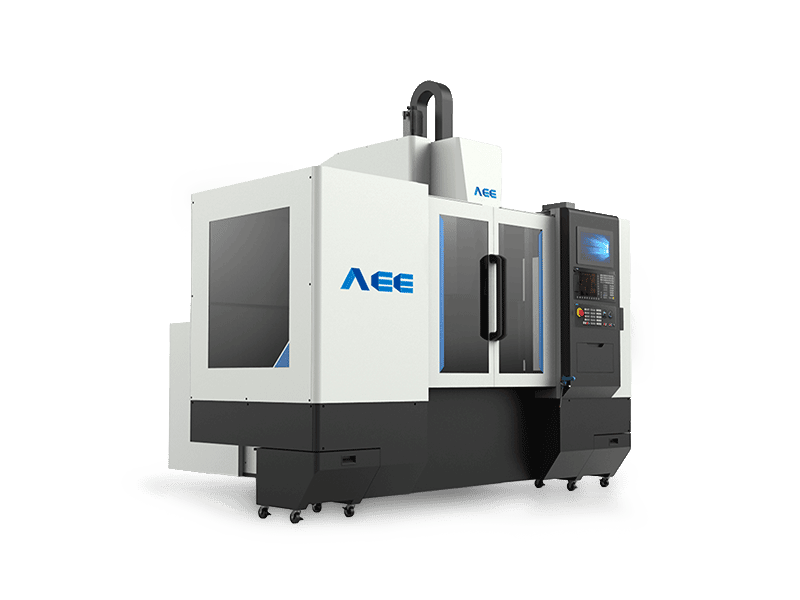
Busbar welding is more demanding than thin cosmetic work because electrical conductors are often wide, thick, or copper-bearing. The machine must hold the joint closed under high axial force while maintaining constant travel speed and tool depth. For short aluminum busbars up to about 8 mm, a rigid C-type machine is usually sufficient. A 12 kW spindle, 112 Nm of torque, and 30 kN of maximum Z-axis force are typical for development work and medium-size parts.
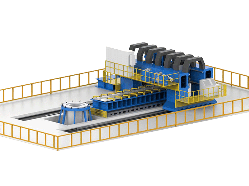
Long aluminum conductor profiles, such as those used in switchgear or bus duct, need a machine with adequate X-axis travel and straightness control. Extra-length straight-profile machines are designed for these seams and should be evaluated for travel accuracy and clamp spacing along the full bar.
For thick aluminum stacks and copper connections, a heavy-load gantry machine is often the safer choice. AEE, for example, offers a heavy-load FSW machine rated for 100 mm single-side aluminum depth and 35 mm single-side copper depth, with a 105 kW spindle and 872 Nm of torque. The high Z-axis force keeps the tool fully engaged in high-conductivity copper, which resists plastic flow more than 6xxx aluminum.
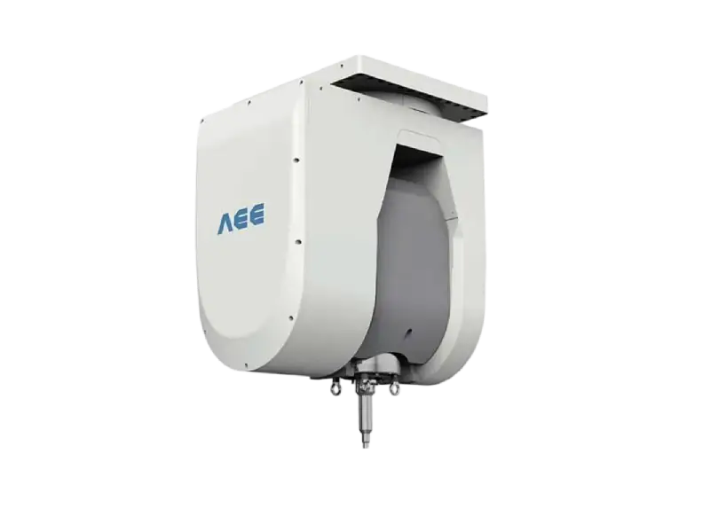
Spindle choice follows the material and thickness. For thin aluminum busbar, a compact spindle is adequate. For copper or thick stacked sections, torque and thermal stability matter more than maximum speed. The available spindle series includes options from 12 kW for light sections to 105 kW for thick multi-layer joints.
Tool selection also drives heat input and root quality. A conventional pin tool works for many straight busbar welds and is available in the same product family as process-specific tools.
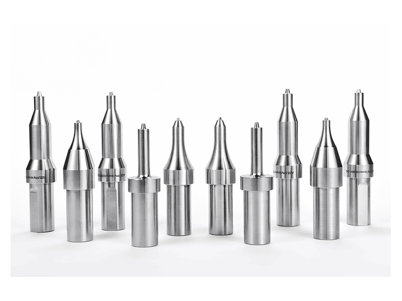
Where surface flash and thinning are unacceptable, a stationary-shoulder tool can help by limiting heat from the shoulder and producing a flatter surface. This is relevant for busbar applications where the joint must fit into a laminated stack or maintain a precise overall thickness.
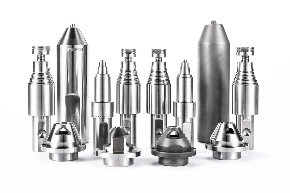
Tooling for a busbar line usually includes more than a basic pin tool. Matched holders, tool cooling, and optional features determine how well the tool survives copper and long aluminum runs. <AEE provides customer with optional features FSW tool> covers optional tool features matched to a specific weld path and material stack.
Heat, Force, and Speed Control in Busbar FSW
FSW for electrical conductors is controlled by the relationship among spindle speed, travel speed, axial force, and tool tilt. The goal is to plasticize enough material to fill the joint without overheating the surrounding conductor. Too little heat leaves an unconsolidated root or tunnel defect. Too much heat creates flash, excessive thinning, or a wide softened zone.
Copper requires a different balance from aluminum. It conducts heat away faster, so the weld zone can cool too quickly if the machine does not maintain enough spindle torque and plunge force. A machine with closed-loop force or torque control is more practical than trying to hold a fixed position alone, because tool wear and thermal expansion change the effective depth during a run.
Process monitoring should record force, torque, spindle speed, travel speed, and tool temperature when available. For qualification, use the same monitoring channels that will run in production, and set alarms around the limits established during feasibility trials rather than around arbitrary global defaults.
Quality Verification for Electrical Busbar Joints
Mechanical weld acceptance alone does not prove that a busbar joint will carry current reliably. Visual, mechanical, and electrical checks answer different questions, and each should be used for the failure mode it can actually detect.
| Check | What it can support | What it does not prove |
|---|---|---|
| Visual and dimensional | Surface continuity, flash, thinning, keyhole location | Internal voids or contact resistance |
| Radiographic or ultrasonic | Volumetric voids, lack of fusion, root defects | Long-term joint resistance under thermal cycling |
| Cross-section macro | Penetration depth, joint contour, interface mixing | Uniform properties along the full weld length |
| Tensile or bend test | Mechanical joint efficiency | Electrical performance |
| Contact resistance or current cycling | Electrical stability and heating behavior | That every future production lot will pass without process controls |
Qualification should use the actual busbar alloy, temper, plating condition, and thickness. A weld proved on a clean 6xxx aluminum sample does not automatically qualify a plated or anodized bar, a different alloy, or a copper-to-aluminum transition. Keep the trial result limited to the material source, joint configuration, and test checks actually completed.
Request an FSW Busbar Feasibility Review
To specify an FSW busbar application, send the alloy and temper, conductor or laminate thickness, joint type, width, production volume, and any electrical acceptance requirement such as contact resistance or thermal cycling. Include the drawing or sample photo and note whether the connection is aluminum-to-aluminum or aluminum-to-copper. Our engineering team can evaluate the material stack against the available machine, spindle, and tooling options and propose a feasibility weld plan before tooling is committed.
Contact Aerospace Engineering Equipment (Suzhou) Co., Ltd. at [email protected] or +86 18325808715.
FAQ
Does FSW work for aluminum-to-copper busbar joints?
Yes, with qualification. FSW is useful for aluminum-to-copper transitions because the low heat input limits intermetallic growth, but the process window is narrow and alloy-specific. The supplier should validate the actual material pair, joint design, and thermal history before production.
What if a conventional FSW tool leaves an exit hole in a closed-loop busbar?
Plan the tool exit. For a closed conductor loop, use a run-off tab, extend the weld outside the current-carrying path, or select a retractable-pin tool that fills the exit hole. The choice depends on geometry and production cost, not on weld strength alone.
What electrical acceptance checks should a busbar weld pass?
At minimum, record the weld parameters and check the joint for surface defects and dimensional change. Then add the checks that match the application risk: cross-section macro for root quality, radiographic or ultrasonic inspection for internal voids, and contact-resistance or thermal-cycling testing for electrical performance.
Can FSW be used on plated or anodized aluminum busbars?
Remove the plating or coating from the weld path. Plating and anodized layers can contaminate the joint, increase tool wear, and hide surface preparation issues. Design the mask or machining step so the final part keeps its coating where current transfer is not welded.
If you’re interested, check out these related articles:
Refill Friction Stir Spot Welding (RFSSW)
AEE provides customer with optional features FSW tool
Customized Dissimilar Material Welding Manufacturers in China
AEE attend 13th International Symposium on FSW in Kyoto, Japan on 21 – 23 May 2024