
FSSW vs Linear FSW Tool Design: Machine Selection Factors
Table of Contents
- Design Differences Between FSSW and Linear FSW Tools
- How FSSW Tool Design Changes Machine Specifications
- Integrating FSSW Tools into an Automated Production Line
- When to Choose FSSW Over Linear FSW for Your Application
- Common Questions About FSSW Tool Selection
- What is the difference between FSSW and refill FSSW tools?
- Can I use a standard FSW machine for FSSW tooling?
- How does tool wear compare between FSSW and linear FSW?
- What material thicknesses can FSSW handle?
- Next Steps for Tool-Machine Matching
The design difference between a friction stir spot welding (FSSW) tool and a linear FSW tool goes far deeper than weld geometry—it directly drives the machine force control architecture needed to sustain reliable production. In spot welding, the retractable pin and compression sleeve must execute a precise, timed sequence that places far higher dynamic demands on the spindle and Z-axis than the steady-state shoulder contact used in linear welds. I have seen production lines stumble because the machine’s force loop could not follow the retraction stroke fast enough, causing inconsistent spot quality and unplanned downtime. This article examines the actual machine-level requirements triggered by FSSW tool design so that production buyers and engineers can avoid specifying a tool their equipment cannot support.
Design Differences Between FSSW and Linear FSW Tools
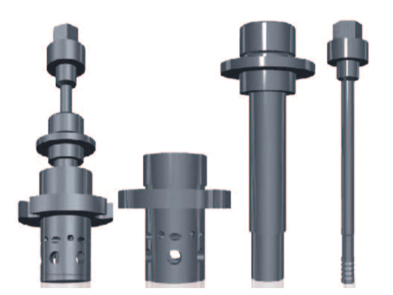
At the tool level, linear FSW uses a single rotating body with a pin and a shoulder that remain in constant contact with the workpiece along the weld path. The shoulder generates frictional heat and contains the plasticized material, while the pin stirs it into a joint. In contrast, an FSSW tool consists of three independently moving components: a rotating pin, a rotating sleeve, and a stationary or moving compression sleeve (also called a clamp). These parts work in a programmed sequence: the clamp first applies pressure to hold the sheets, then the pin and sleeve plunge into the material, rotate to stir, and finally the pin retracts into the sleeve to refill the exit cavity, leaving a nearly flush surface with no keyhole.
This mechanical complexity is what eliminates the keyhole, but it also introduces the tool forces that change the machine equation. Where a linear FSW tool requires the machine to maintain a steady axial force of 5–15 kN over long continuous runs, an FSSW tool cycle involves rapid force spikes during plunge, dwell, and retraction—often within fractions of a second. The table below summarizes the key design differences.
| Design Aspect | Linear FSW Tool | FSSW Tool |
|---|---|---|
| Active components | Single-piece pin + shoulder | Separate pin, rotating sleeve, compression clamp |
| Force profile | Steady-state axial load | Rapidly varying axial/rotational load |
| Keyhole | Always present (unless retractable tool) | Eliminated by pin retraction |
| Material flow | Continuous along weld line | Localized, repeated at each spot |
| Typical cycle time | Continuous; few meters/min | 1–3 seconds per spot |
For applications where a keyhole-free surface finish is mandatory, <Refill Friction Stir Spot Welding (RFSSW)> covers the tool kinematics and material flow that fully consolidate the spot without the slight surface mark left by standard FSSW tools.
How FSSW Tool Design Changes Machine Specifications
The most direct consequence of switching from linear to spot welding tools lands on the spindle. In linear FSW, the spindle primarily provides torque at a relatively constant speed, while the machine frame supplies the axial force. In spot welding, the spindle must simultaneously deliver torque and react to rapidly changing axial forces, often with a control loop frequency well north of 1 kHz to maintain position and force accuracy. I have observed that spindles designed for continuous-duty linear welding—robust, well-cooled, but with a slower force servo—can overshoot or oscillate during the retraction stroke of an FSSW tool, leaving inconsistent spot fill.
From a specification standpoint, buyers should examine three spindle parameters: (1) the dynamic axial force response time—how quickly the spindle can ramp from zero to full plunge force and back; (2) the torque characteristics at low speed, because many spot welds are performed at 800–1500 rpm where available torque may be different from the rated peak; and (3) the tool clamping interface, since FSSW tools often require a BT40 or BT50 holder with precise runout to avoid sleeve wear. Our spindle series, for example, ranges from 12 kW units with 112 Nm torque for aluminum up to 8 mm, to 31 kW spindles handling 25 mm plate. But choosing the right one is less about continuous power and more about whether the force loop can stay stable through the tool’s cyclical motion.
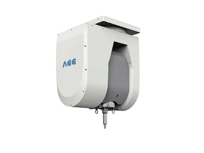
Machine rigidity also matters more than many first-time buyers realize. During FSSW tool retraction, the upward force impulse can momentarily deflect a lightly built Z-axis, altering the very gap the compression sleeve is trying to control. In our experience with automotive production lines using C-type machines, a frame stiffness of at least 30 kN/mm in the Z-direction is a practical starting point for consistent spot quality on 2–4 mm aluminum stacks.
If your program involves multi-layer aluminum stack-ups that demand consistent spot weld strength, confirming your spindle’s force control bandwidth before finalizing the tool specification is a step that can prevent months of troubleshooting. Reach out at [email protected] for a compatibility assessment.
Integrating FSSW Tools into an Automated Production Line
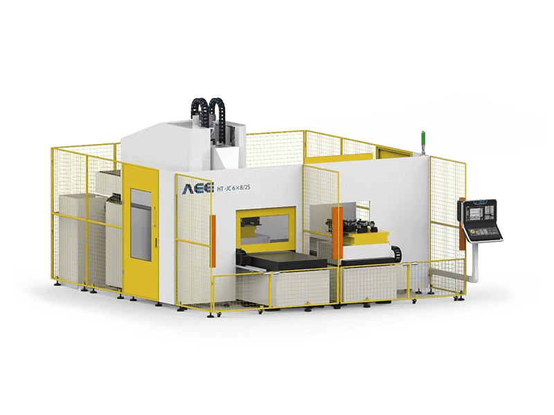
Beyond the spindle and frame, integrating an FSSW tool into a full production line means rethinking how part clamping, positioning, and tool servicing work. In linear FSW, the workpiece is rigidly clamped to a backing plate, and the tool travels along a path. In spot welding, the tool sits stationary for 1–3 seconds at each point while the clamp pressure must be maintained without workpiece movement. This change often calls for dedicated spot-welding cells or a machine like our FSSW model, which is purpose-built with a compact worktable and an integrated clamp force system.
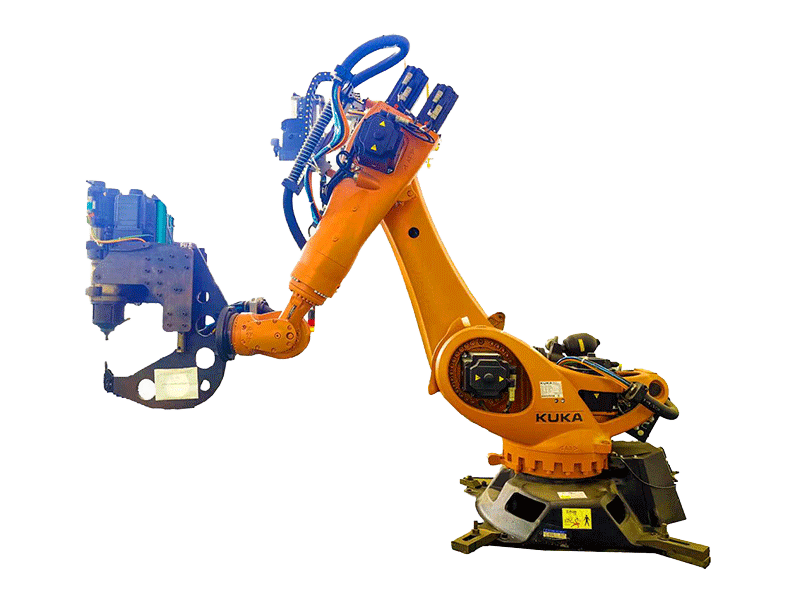
For lines that produce multiple part numbers, tool changeover time becomes a hidden cost driver. A linear FSW tool might run thousands of meters before needing replacement, whereas an FSSW tool can wear faster due to the cyclic loading and sleeve friction. Implementing quick-change tooling systems can cut swap times from 20 minutes to under 5 minutes, directly improving OEE.
For high-mix production environments where tool changeover eats into line availability, <AEE provides customer with optional features FSW tool> details how features like quick-change clamping systems and integrated cooling channels can reduce tool swap time by more than half, keeping smaller batch runs economically viable.
When to Choose FSSW Over Linear FSW for Your Application
The tool choice is not a matter of better versus worse but of matching the joining task to the process physics. Buyers should weigh four criteria:
- Joint configuration: FSSW is designed for lap joints; linear FSW handles butt, lap, T-joint, and corner welds. If your product mainly involves spot welds on overlapped sheets—such as automotive body panels or battery module busbars—FSSW is the natural fit.
- Weld length required: If you need a continuous hermetic seal, linear FSW remains the only option; FSSW cannot produce a continuous seam.
- Cycle time and automation: For high-volume spot-intensive parts, a dedicated FSSW machine with automated part positioning can achieve 45–60 spots per minute, whereas adapting a linear machine may cap at 15–20 spots per minute due to repositioning delays.
- Surface finish and post-processing: FSSW delivers a flush or nearly flush surface that often requires no grinding or machining, reducing downstream cost.
| Selection Factor | Linear FSW Shoulder Tool | FSSW Tool |
|---|---|---|
| Joint type | Butt, lap, T-joint, corner | Lap only (single or multi-layer) |
| Continuous seam | Yes | No |
| Spot weld capability | Limited (requires special retractable tool) | Core function |
| Per-spot cycle time | N/A | 1–3 seconds |
| Surface finish | Slight shoulder mark | Flush, keyhole-free |
| Machine type | Gantry, C-type, heavy-load, 3D | Dedicated spot welder or adapted C-type with force control |
Common Questions About FSSW Tool Selection
What is the difference between FSSW and refill FSSW tools?
Refill FSSW tools use a more complex sleeve and pin mechanism to fully backfill the exit hole, leaving a smooth surface that matches the parent material, while standard FSSW leaves a slight depression. The choice depends on whether your product’s aesthetic or fatigue requirements can tolerate a shallow indentation. In our lab tests on 2 mm 6061-T6, refill FSSW improved fatigue life by roughly 15% over standard FSSW due to reduced stress concentration at the spot center.
Can I use a standard FSW machine for FSSW tooling?
It depends on the machine’s Z-axis force control capability. A standard C-type or gantry machine with a force-controlled spindle and sufficient frame stiffness can be adapted for FSSW if it allows programmable axial force profiles. However, machines designed only for position control with a passive force limiter will struggle to execute the precise pin retraction sequence needed for consistent refill. If you are considering adapting an existing machine, verify that the CNC can accept a force setpoint table synchronized with spindle rotation.
How does tool wear compare between FSSW and linear FSW?
In production lines we have supported, FSSW tool life is typically 30–50% shorter than linear FSW tools when welding aluminum, primarily due to the cyclic sleeve friction and the thermal shock from repeated plunges. With optimized cooling channels in the tool holder and careful plunge depth control, we have extended FSSW tool life to over 15,000 spots on 6000-series aluminum before requiring rework.
What material thicknesses can FSSW handle?
It is a common misconception that FSSW is limited to thin sheet under 2 mm. In practice, we routinely spot weld 3–6 mm sections in single plunges, and with multi-step plunge cycles, thicknesses up to 8 mm are achievable with the right spindle torque and clamping force. The key is matching the sleeve diameter and plunge depth to the stack-up. Share your material stack-up and target throughput, and we will confirm the achievable spot weld strength for your application—[email protected].
Next Steps for Tool-Machine Matching
Matching an FSSW tool to a machine is not a catalog exercise—the dynamic interaction between the tool’s retractable mechanism and the spindle’s force servo determines whether your line delivers 45 JPH or stumbles at single-digit rates. At Aerospace Engineering Equipment, we have built and integrated hundreds of FSW and FSSW machines globally, and we are often asked to solve problems that began with an incompatible tool-machine pairing.
If you are specifying a new FSSW tool or upgrading an existing line, send us your part drawing and production target. Our engineering team will review the tool design, propose the spindle and frame configuration that matches your cycle-time goal, and if needed, we can run sample welds at our Suzhou facility to validate the process before you commit to equipment.
Direct email: [email protected] | Phone: +86 18325808715
If you’re interested, check out these related articles:
Customized Dissimilar Material Welding Manufacturers in China
Refill Friction Stir Spot Welding (RFSSW)
AEE attend 13th International Symposium on FSW in Kyoto, Japan on 21 – 23 May 2024
AEE provides customer with optional features FSW tool