
FSSW Tool Design: Pin, Shoulder, and Plunge as One System
Table of Contents
- FSSW tool design targets before you set dimensions
- Pin length selection and material flow control
- Shoulder diameter and heat input management
- Plunge depth optimization and cycle repeatability
- Confirming FSSW tool geometry before tooling release
- Common questions about FSSW tool design
- Does a longer pin always increase spot strength?
- How much shoulder diameter is too much?
- Can the same FSSW tool handle 1.0 mm, 2.0 mm, and 3.0 mm stacks?
- Why does plunge depth affect tool wear more than pin length?
FSSW tool design is not a geometry exercise to copy from a similar part. Pin length, shoulder diameter, and plunge depth determine material flow, heat input, and spot-to-spot repeatability before the first weld cycle starts. Most reference content treats these dimensions separately, but on a production line they fail as a package. A pin that is 0.3 mm too short will not be corrected by deeper shoulder penetration, and an oversized shoulder can create flash exactly when the pin length is right. I approach FSSW tool geometry as one coupled system, because that is how the problems actually show up in tooling trials.
FSSW tool design targets before you set dimensions
Three dimensions define most of the process window. Pin length controls how deep the rotating pin stirs the upper and lower sheets at the faying surface. Shoulder diameter controls the frictional heat generated at the workpiece surface and the forging area that closes the spot. Plunge depth sets the final shoulder contact pressure and the amount of material displaced. These dimensions cannot be optimized in sequence because changing one moves the acceptable range for the other two. In our FSSW tool line, the working thickness range is 1.0 to 6.0 mm for common aluminum alloys, magnesium alloys, and aluminum to steel combinations, but the tool geometry must be defined for each stack-up rather than selected from a single standard.
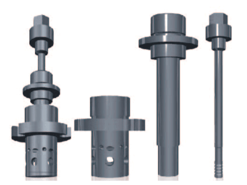
The table below is a starting geometry window for 6xxx aluminum lap joints. It is not a universal recipe. Machine stiffness, spindle speed, and clamping force shift each value.
| Total stack thickness | Pin length target | Shoulder diameter target | Plunge depth below top sheet |
|---|---|---|---|
| 2.0 mm | 1.7 mm | 10 mm | 0.20 mm |
| 3.0 mm | 2.6 mm | 12 mm | 0.25 mm |
| 4.0 mm | 3.5 mm | 13 mm | 0.30 mm |
| 6.0 mm | 5.3 mm | 15 mm | 0.35 mm |
These numbers assume a rigid machine with force-controlled spindle and flat, fully clamped sheets. If the sheets are not held flat, the best geometry will still produce inconsistent contact.
Pin length selection and material flow control
Pin length determines whether the rotating pin reaches the lower sheet and carries material across the lap interface. If the pin is too short, the pin tip stays inside the upper sheet and only superficial stirring occurs. The result looks acceptable from the top but fails shear testing at the faying surface. If the pin is too long, it approaches or pierces the bottom surface, producing a thin-skinned spot, reverse-side flash, or tool contact with the backing plate. In production tools I keep 0.2 to 0.7 mm of unmixed lower-sheet material beneath the pin tip for aluminum stacks between 2 and 6 mm, with the larger remaining thickness on thicker stacks. This keeps the bottom surface intact while still transferring load through the mechanically interlocked layer.
Alloy temper changes this window. Soft 5xxx and 6xxx grades tolerate a longer pin because material flow is easier. High-strength 7xxx and aluminum to steel combinations require a shorter pin relative to total stack thickness and a more careful shoulder radius to avoid cracking at the spot edge. Dissimilar pairs that include steel usually run with the pin end positioned just above the steel sheet, so the aluminum carries plasticized material while the steel remains below the stir zone. A pin that is 0.2 mm too long in this condition can cut a shallow groove into the steel and create a discontinuous bond line that passes visual inspection but fails in fatigue.
Shoulder diameter and heat input management
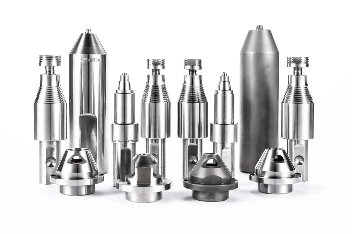
Shoulder diameter is the primary heat input control in FSSW. A larger shoulder increases the contact area, raises frictional power at a given spindle speed and axial force, and flattens the spot surface. It also broadens the process window for softer alloys by spreading heat across a wider zone. The trade-off is material displacement and flash. A shoulder that is too wide for the stack-up pushes softened material outward, leaves a deep ring around the spot, and can create an edge lip that must be removed before painting or sealing.
For 1.0 to 3.0 mm aluminum stacks, shoulder diameters in the 9 to 12 mm range work well. For 4 to 6 mm stacks, 13 to 16 mm is a more practical starting point. If the machine has limited axial force capacity, a smaller shoulder is often the safer choice because less contact area means the available force reaches a higher contact pressure. I would rather reduce shoulder diameter than raise plunge depth to compensate for a low-force spindle. Raising plunge depth increases thinning at the spot center and shortens tool life without solving the underlying pressure limit.
If your application pairs a thin top sheet with a thicker lower sheet or mixes aluminum with steel, shoulder diameter and pin length have to be confirmed as a pair. Send your stack-up thicknesses and target shear strength to [email protected] and we will check geometry before tooling release.
Plunge depth optimization and cycle repeatability
Plunge depth sets the final shoulder pressure and the amount of material displaced from the stir zone. Too little plunge produces a shallow forged region, low bond area, and high variation because small changes in sheet thickness or clamping become a large fraction of the total engagement. Too much plunge over-thins the joint, generates excessive flash, and accelerates wear on the shoulder and sleeve. The practical target is the minimum plunge depth that produces a stable shoulder ring and repeatable spot diameter without visible thinning below the lower sheet.
For aluminum lap joints I usually start with plunge depth between 0.20 and 0.35 mm below the top sheet surface and adjust only after sectioning the first three to five spots. If the interface shows incomplete mixing, the first correction is usually not more plunge depth. It is more pin length or a different pin profile. If the spot shows reverse-side bulging or a ring of expelled material, plunge depth is too high and should be reduced before changing spindle speed.
When a production spot cannot tolerate an exit keyhole or must sit flush for a sealing surface, a fixed-pin geometry may not be enough. <Refill Friction Stir Spot Welding (RFSSW)> covers how a moving sleeve and pin backfill the exit zone, and why that shifts plunge depth and pin length targets from a simple strength calculation to a surface finish and fatigue requirement.
Confirming FSSW tool geometry before tooling release
FSSW tool geometry is a low-cost place to make a high-cost mistake. A tool ordered from a similar part drawing without confirming pin length, shoulder diameter, and plunge depth for the actual stack-up will produce weak spots, inconsistent cycles, or both. If your project involves aluminum to steel joints, closed contours, thin top sheets, or a production line that cannot accept keyhole finishing, it is worth confirming tool geometry before the tooling order is released. Send your top sheet thickness, bottom sheet thickness, alloy grades, and target joint performance to [email protected] or call +86 18325808715. We will review the stack-up and return a geometry proposal with starting parameters for your machine.
Common questions about FSSW tool design
Does a longer pin always increase spot strength?
No. Strength increases only until the pin stirs across the lap interface and creates a continuous bonded zone. A pin that is too long then becomes a liability because it thins the lower sheet, raises reverse-side flash, and shortens tool life. The useful rule is to lengthen the pin only while cross-sections still show the lower sheet intact and the faying surface fully broken up. Once those two conditions are met, further pin length usually adds cost and cycle variation, not strength.
How much shoulder diameter is too much?
It depends on stack thickness and axial force capacity, but a clear failure signal is flash that cannot be removed without secondary work. When the shoulder is too wide, peripheral material heats and softens without contributing to bond formation. The spot begins to look like a wide shallow ring instead of a forged plug. I set the upper shoulder limit at a diameter that still allows visible shoulder contact for the full spot edge without pushing material beyond the original sheet surface by more than a small lip.
Can the same FSSW tool handle 1.0 mm, 2.0 mm, and 3.0 mm stacks?
A better question is whether your cycle time and strength target let one geometry serve multiple stack-ups. A single tool can often cover a narrow thickness band if pin length and plunge depth are set for the thickest stack, but the thinner stack then runs with excess plunge and more flash. If the product mix is wide or the thinner joint is strength-limited, two tools are usually cheaper than chasing a compromise that fails both extremes.
Why does plunge depth affect tool wear more than pin length?
Many engineers assume pin length has the larger wear effect, but the sleeve and shoulder contact pressure usually dominate. Plunge depth directly increases surface contact stress, expelled material, and local temperature at the tool shoulder. A pin that is too long may break or score the lower sheet, but it does less gradual damage than a 0.1 mm plunge depth increase repeated over thousands of cycles. If your process runs multiple stack-ups or aluminum to steel combinations, share your thickness range and alloy grades with [email protected] and we will confirm whether one tool or two tools is the lower-risk path.
If you’re interested, check out these related articles:
Customized Dissimilar Material Welding Manufacturers in China
Refill Friction Stir Spot Welding (RFSSW)