
FSSW for Aluminum Sheet Metal: Thickness and Key Parameters
Table of Contents
- FSSW for Aluminum Sheet Metal Covers a Practical 1 mm to 6 mm Window
- Thickness Changes FSSW for Aluminum Sheet Metal More Than Power Setting
- Starting Parameters for Aluminum Sheet Stacks Need Verification
- Thin Stack Adjustments
- Thick Stack Adjustments
- Multi-Material Stack Adjustments
- Tool Geometry Sets the Real Aluminum Sheet Thickness Capability
- Aluminum Sheet Buyers Need to Confirm the Weld Specification Before Tooling
- Procurement Teams Ask These Questions About FSSW for Aluminum Sheet Metal
- Does FSSW work on 1 mm aluminum sheet?
- Can FSSW replace resistance spot welding on aluminum body panels?
- Why does the same parameter set fail on a different coil of the same alloy?
- Is refill FSSW required for aluminum sheet or is conventional FSSW enough?
FSSW for aluminum sheet metal is a production-ready process in the 1 mm to 6 mm thickness range, but most early failures come from treating it like a simple replacement for resistance spot welding. The real decision is not whether the tool can plunge, but whether your stack, surface condition, and clamping setup keep the spot geometry stable as the sheets thin or thicken. I have watched too many aluminum sheet programs start with good parameters and lose cycle time to edge distortion and material thinning because the process window was copied from a different stack.
FSSW for Aluminum Sheet Metal Covers a Practical 1 mm to 6 mm Window
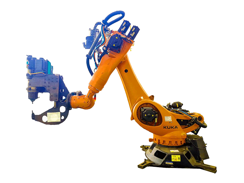
FSSW for aluminum sheet metal sits in a practical production window from 1.0 mm to 6.0 mm total stack thickness for standard aluminum grades. That is not a soft guideline. Tool geometry, sleeve travel, and process force are usually sized around this band, and once you move outside it the failure modes change: thin stacks tear at the edge, thick stacks overheat and soften the surrounding material. For most automotive brackets, battery module covers, and thin-wall enclosures, the process is not limited by spindle power. It is limited by how well the spot formation is controlled while the surrounding sheet is clamped.
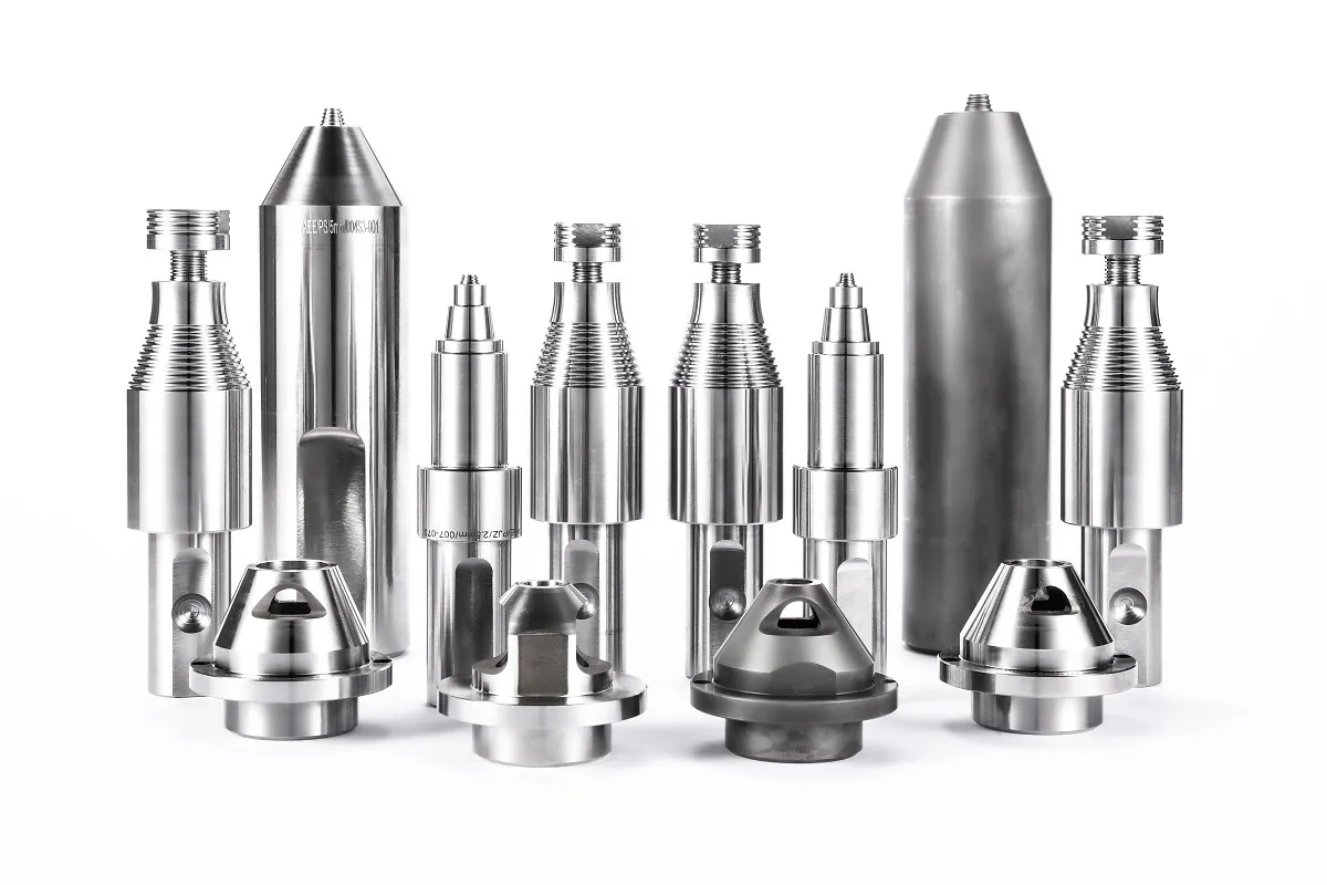
The FSSW tool we run uses a compression sleeve, stir sleeve, and stir pin. The three-part arrangement backfills and levels the spot rather than leaving an open keyhole. On sheet metal, that surface result translates directly into crack resistance and appearance. The same tool family covers common 4XXX, 5XXX, and 6XXX aluminum alloys and can also apply to magnesium and aluminum-steel dissimilar stacks.
Thickness Changes FSSW for Aluminum Sheet Metal More Than Power Setting
When the stack changes from two 1 mm sheets to a single 4 mm sheet, the first thing I look at is not rotation speed but the thermal mass and upset path. Thin stacks cool quickly because the fixture and surrounding sheet draw heat away faster than the plasticized material forms. That requires a slightly higher surface speed so the material stays plastic long enough for the sleeve to move. Thick stacks hold heat, so a long dwell at high speed can produce flash, over-ageing, or a softened zone larger than the spot itself.
Edge distance is the hidden variable. If the spot center sits less than about three times the sheet thickness from the flange edge, the sleeve upset can push material outward and tear the edge land. I have seen this on 1 mm enclosures where the spot looked good in the center but the outer sheet cracked at the edge after trimming. A thicker nominal sheet does not automatically give you more tolerance here because the real limit is the unsupported edge land, not the total stack height.
Refill tooling changes the spot surface and fatigue behavior, which matters when an aluminum sheet assembly with visible outer panels cannot accept an exit hole. <Refill Friction Stir Spot Welding (RFSSW)> covers the sleeve and pin sequence that backfills the weld spot and why keyhole elimination is usually a design requirement rather than a cosmetic upgrade.
Starting Parameters for Aluminum Sheet Stacks Need Verification
Parameter values from a published chart are a starting point, not a release parameter. Sheet temper, coating, fixture stiffness, and even coil-to-coil surface condition move the real window. The table below shows the bands I use when beginning process development on AEE equipment for common aluminum sheet stacks.
| Stack configuration | Total thickness | Rotation speed | Plunge depth | Dwell time | Axial force |
|---|---|---|---|---|---|
| Two 1 mm 6xxx sheets | 2.0 mm | 2000 to 3000 rpm | 2.0 to 2.4 mm | 1.5 to 2.5 s | 3 to 5 kN |
| Two 2 mm 5xxx sheets | 4.0 mm | 1500 to 2200 rpm | 3.8 to 4.4 mm | 2.0 to 3.5 s | 5 to 8 kN |
| Two 3 mm 6xxx sheets | 6.0 mm | 1200 to 1800 rpm | 5.2 to 6.0 mm | 3.0 to 5.0 s | 8 to 12 kN |
| 1.5 mm 6xxx to 1.0 mm steel | 2.5 mm | 1800 to 2500 rpm | 2.0 to 2.6 mm | 2.0 to 3.0 s | 5 to 8 kN |
For thin stacks, plunge depth and dwell time usually matter more than spindle power. For thick stacks, axial force and sleeve travel become the dominant controls because the lower sheet must be stirred and backfilled without excessive flash.
Thin Stack Adjustments
Thin stacks below about 2 mm need a shorter plunge increment and a faster retract. If the sleeve spends too long in the material, the partially cooled spot can drag when the tool retracts. We shorten dwell before increasing force.
Thick Stack Adjustments
Thick stacks above about 4 mm require a higher downforce and often a slightly lower speed to avoid surface flash. The key check is not spot diameter alone but cross-section integrity through the bottom sheet. A spot that looks acceptable on the top sheet may still show incomplete mixing in the lower layer.
Multi-Material Stack Adjustments
When the stack combines aluminum with steel, the process window is not about thickness alone. The aluminum side governs most of the flow, but tool wear and intermetallic growth control the upper temperature limit.
When the stack mixes aluminum with steel or magnesium, the process window is no longer only about sheet thickness. <Customized Dissimilar Material Welding Manufacturers in China> explains how material pairs change tool life, intermetallic control, and the qualification work required before production.
If your program involves a 6xxx top sheet over a 5xxx lower sheet or an aluminum-to-steel stack, it is worth confirming the plunge depth and dwell time on your actual sheet combination before finalizing tooling. Write to [email protected] with your stack gauge, spot diameter target, and joint configuration, and we can check the practical parameter window.
Tool Geometry Sets the Real Aluminum Sheet Thickness Capability
The machine can supply force, but the tool decides where that force goes. For FSSW, the three main elements are the compression sleeve, stir sleeve, and stir pin. The pin creates the stirred zone, the compression sleeve controls the forged surface, and the stir sleeve moves the plasticized material into the pin cavity.
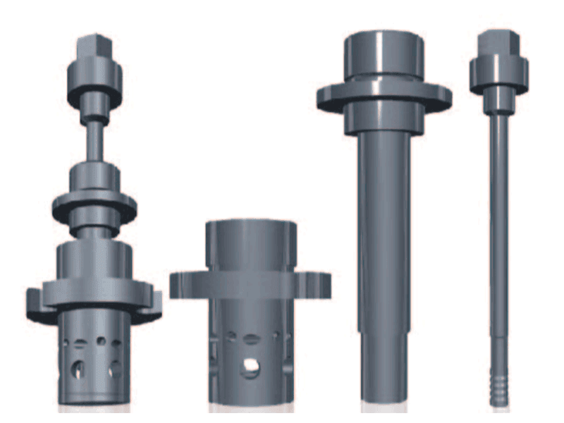
A tool designed for 1 mm sheet has a short pin and a tight sleeve bore, so the spot stays small and the heat input is limited. A tool for 6 mm sheet has a longer pin, a larger bore, and more travel. If you run a long-pin tool on thin stock, you get excessive plunge and edge deformation. If you run a short-pin tool on thick stock, the lower sheet sees too little mixing and the joint separates under peel load.
AEE supplies the FSSW tool for aluminum alloy 4XXX, 5XXX, and 6XXX sheet and for aluminum-steel dissimilar combinations from 1.0 mm to 6.0 mm. The tooling decision should be made from the actual joint stack and load condition, not from the machine specification alone.
Tooling options are not only about material choice. Sometimes the spot diameter and sleeve retention features decide how long a tool lasts in production. <AEE provides customer with optional features FSW tool> covers practical tool modifications for different joint configurations and what changes when you move from open coupon work to a constrained production fixture.
Aluminum Sheet Buyers Need to Confirm the Weld Specification Before Tooling
The most expensive mistake in an aluminum sheet FSSW project is freezing the tool and fixture before the actual sheet surface and stack are tested. Coated sheet, mill finish, gauge variation, and anodized or conversion-coated surfaces all shift heat input and backfill behavior more than most parameter charts suggest.
At AEE, we use sample welding on your actual sheet material to confirm spot diameter, shear strength, surface finish, and edge distance behavior before releasing tooling. The test piece is small, but the information it gives you prevents a bad fixture design from becoming an expensive production constraint.
Send your alloy grade, stack construction, target spot diameter, and required production rate to [email protected] or call +86 18325808715. We will confirm the FSSW parameter window and recommend the correct tool configuration for your aluminum sheet combination.
Procurement Teams Ask These Questions About FSSW for Aluminum Sheet Metal
Does FSSW work on 1 mm aluminum sheet?
Yes. One millimeter aluminum sheet falls inside the practical FSSW window, but the tooling and clamping need more attention than 2 mm or 3 mm stock. The pin and sleeve sizes must match the thin sheet, the edge distance must be increased relative to sheet thickness, and the fixture should hold the back side close to the spot. If those conditions are in place, the process produces a small, repeatable spot without burning through. On a loose fixture or with a long-pin tool borrowed from a thicker program, the same sheet will tear or deform.
Can FSSW replace resistance spot welding on aluminum body panels?
A common assumption is that resistance spot welding is always faster on aluminum, but that ignores tip wear, surface cleaning, and energy cost. FSSW needs no filler, produces a flat surface spot, and gives higher shear and fatigue resistance than resistance spot welding for many 5XXX and 6XXX sheet stacks. The tradeoff is that the cycle time and fixture stiffness are different. If the panel has a visible outer surface and a strict fatigue requirement, FSSW is often the better choice. If the joint is hidden and throughput is the only driver, the comparison needs a full production-cycle study.
Why does the same parameter set fail on a different coil of the same alloy?
It depends on the surface condition and temper path more than the alloy number alone. Mill finish, oil, oxide thickness, and the actual gauge tolerance change how the sleeve and pin transfer heat. A coil at the top of the thickness tolerance can hold more material than the nominal calculation expects, which increases the backfill volume and changes the plunge depth. A coil with heavier oxide needs more initial stirring capacity before the material becomes plastic. That is why we verify parameters on the production coil or at least on a sample from the same lot.
Is refill FSSW required for aluminum sheet or is conventional FSSW enough?
In the sheet programs we have supported, the choice usually comes down to the outer surface and fatigue load. Conventional FSSW leaves a central exit hole, which can be acceptable inside a bracket or behind a cover. Refill FSSW closes that hole and gives a flat, more fatigue-resistant spot, which matters on visible closures, sealed joints, and load-bearing outer panels. If the application is structural or requires consistent surface quality, we usually specify refill from the start rather than trying to convert later. Share your surface finish requirement and load case, and we will confirm whether refill or conventional tooling fits your aluminum sheet assembly.
If you’re interested, check out these related articles:
AEE provides customer with optional features FSW tool
Customized Dissimilar Material Welding Manufacturers in China
Refill Friction Stir Spot Welding (RFSSW)
AEE attend 13th International Symposium on FSW in Kyoto, Japan on 21 – 23 May 2024