
Friction Stir Welding Machine Specs Buyers Must Verify
Table of Contents
- Which Welding Thickness Rating Actually Applies to Your Part
- Reading Spindle Torque, Power and Z Force Together
- Force Control or Position Control and When Each Fits
- When position control is enough
- When force control earns its cost
- How Machine Architecture Follows Part Geometry
- What Positioning Accuracy and Repeatability Do Not Prove
- Tool Interface, Tooling and Changeover as Specifications
- What to Verify Before You Accept the Specification
- Send Your Part Details for a Specification Review
- FAQ
- What welding thickness should I specify for an FSW machine?
- Is higher spindle rotation speed better for friction stir welding?
- Do I need force control or position control?
- What floor space and foundation does an FSW machine need?
- Can one machine weld aluminium and copper?
Most friction stir welding machine specifications are easy to compare and hard to verify. Two suppliers can both quote an 8 mm aluminium capacity, 30 kN of axial force, and a 12 kW spindle while their machines behave differently on the same part, because a data sheet number describes a capability, not the record that proves it. The purchase turns on a narrower set of figures and on the evidence behind each one: what the number measures, which alloy and joint it applies to, and what the supplier can show when your sample weld is sectioned. This guide works through those specifications in the order a purchase actually resolves them.
Which Welding Thickness Rating Actually Applies to Your Part
Maximum welding thickness is the first number buyers compare and the one most often read out of context. On a friction stir welding machine it describes how deep the tool can stir in a single pass, in a stated material, with a tool and parameter set the supplier has qualified. A catalogue that lists 8 mm for a compact platform and 100 mm for a heavy gantry is not offering the same product at two prices. It is describing two different force and torque envelopes, two structure sizes, and two tool families.
Ask whether the rating is single-side penetration or a weld made from both faces. Aerospace Engineering Equipment’s heavy-load platform publishes 100 mm of single-side aluminium penetration, 190 mm when the joint is welded from both sides, and 35 mm for copper from one side. A buyer who needs 60 mm of aluminium can reach that figure through a 100 mm class machine in one pass, or through two passes from opposite faces on a smaller machine. The two routes differ in fixture cost, distortion, floor space, and cycle time, and neither is automatically correct.
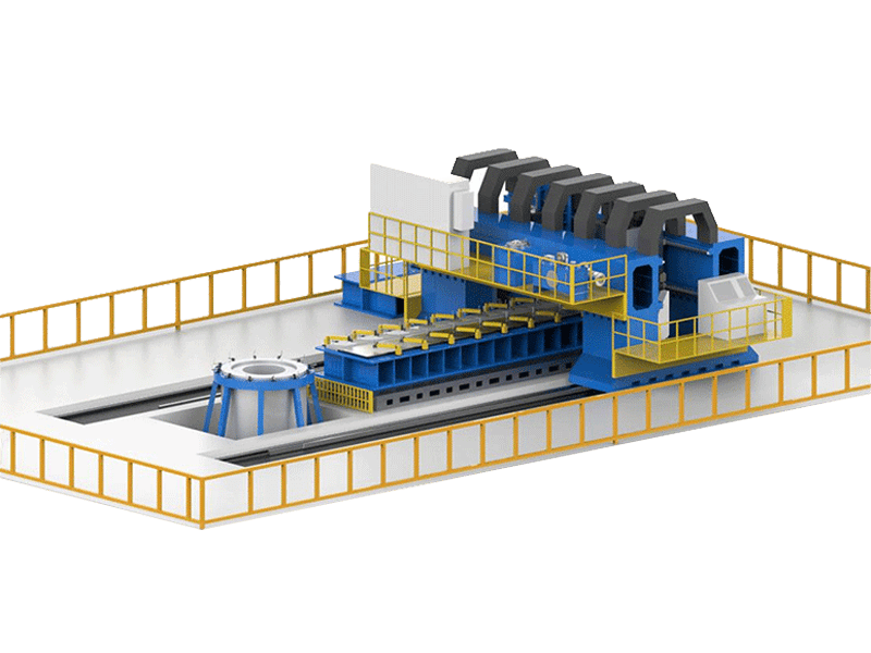
The alloy matters as much as the thickness. Published thickness bands are usually written against 6XXX series aluminium, the common production case. High-strength 2XXX and 7XXX alloys, magnesium, and copper need more force and different tool geometry, and the same platform will weld them at a smaller depth. The copper figure above makes the point: on a machine rated for 100 mm of aluminium, copper reaches 35 mm. Treat any thickness rating that does not name the alloy as incomplete.
Dissimilar joints add a second constraint, because the two metals conduct heat and deform at different rates under the same tool. The thickness rating then applies to the softer member only, and the harder member sets the tool wear rate.
Dissimilar joints are usually specified as a manufacturing programme rather than a single machine purchase. <Customized Dissimilar Material Welding Manufacturers in China> covers customized dissimilar material welding and the questions buyers bring to that kind of project.
The figures below are published catalogue values for the spindle classes in one manufacturer’s range, not independent test results. They show how the numbers move together, and the fourth column shows what a buyer should not read into them.
| Published thickness band | Spindle figures at that band | What the figures support | What they do not prove |
|---|---|---|---|
| 1 to 8 mm | 4,000 rpm, 12 kW, 112 Nm, 30 kN axial force | A compact platform can weld this band in common aluminium alloys | That one parameter set covers both 2 mm sheet and 8 mm plate, or that 7XXX alloys behave the same way |
| 2 to 16 mm | 2,500 rpm, 25 kW, 208 Nm, 50 kN | Mid-thickness plate on a gantry platform | That a 16 mm seam runs at the same travel speed as an 8 mm seam |
| 2 to 25 mm | 2,000 rpm, 31 kW, 257 Nm, 60 kN | Thick plate work with larger shoulder tools | Interchangeability with a 16 mm class machine on an existing fixture |
| 2 to 40 mm | 1,500 rpm, 58 kW, 482 Nm, 80 kN | Heavy aluminium sections at lower rotation speed | That copper or steel of similar thickness falls inside the same window |
| 2 to 100 mm | 1,000 rpm, 105 kW, 874 Nm, 200 kN | Single-side 100 mm aluminium and 35 mm copper on a heavy gantry | That a 100 mm rating means full penetration on every alloy at every thickness |
Reading Spindle Torque, Power and Z Force Together
Three numbers set the working envelope: spindle torque, spindle power, and the axial force the frame can push through the tool. They are not independent, and a quotation that presents them separately invites a comparison that does not hold.
Torque and rotation speed together produce power at the tool. Axial force determines whether the tool stays in the material and generates enough friction heat to plasticise it. As plate gets thicker, the shoulder and pin grow, contact area increases, and the force needed to stir the section rises. Rotation speed usually falls at the same time, because a larger tool at high speed overheats the surface before the root is stirred. That is why one product family can list 4,000 rpm with 112 Nm at the thin end and 1,000 rpm with 872 Nm at the thick end. A supplier quoting high rotation speed and high torque on a light frame is either describing a peak rating or a machine that will not hold both values continuously.
Ask whether the rating is continuous or intermittent, and how the spindle is cooled. Grease lubrication covers the smaller spindles; the heavy-load heads in the same range use hydraulic cooling because the heat path from tool to bearing is longer and the duty cycle is heavier.
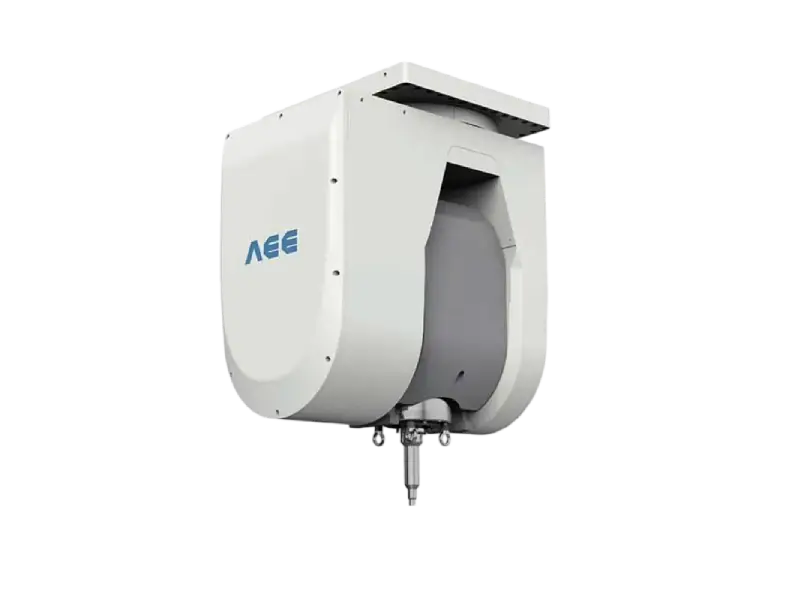
Force capacity has a structural consequence worth checking. Axial force has to be reacted somewhere, and the machine mass gives a rough indication of how much structure is carrying it. A compact C-type platform with 30 kN of Z force lists around 6,000 kg; a 100 mm class double-gantry platform with 200 kN lists around 120,000 kg. Mechanical structures are sized by force and stiffness together, so compare force per unit of mass across quotations. A very high force rating on a light frame points to a deflection question, and frame deflection under load is what moves the tool relative to the seam.
Two practical checks follow. Ask for the frame deflection or stiffness at rated force if your weld tolerance depends on it, and confirm that the published force is available during the whole seam, not only at the start.
Force Control or Position Control and When Each Fits
The control mode decides what the machine holds constant while the tool is in the material, and the two modes fail in different ways.
Under position control the Z axis is commanded to a depth. The machine returns to that depth on every part, and the axial force varies with plate thickness, fixture compliance, and the thermal state of the machine. If the plate runs 0.3 mm thick in one area, the tool sits deeper relative to the surface and force rises.
Under force control the machine holds axial force and the Z axis follows the material. Plunge depth varies, force does not. On extruded profiles with wall variation, castings with draft, or long panels that deflect between clamps, this is usually the difference between a stable seam and a variable one.
When position control is enough
Machined plate with tight thickness tolerance, a rigid fixture, and a stable thermal environment suits position control, and it is simpler to program and to audit. The condition is that the part tolerance is smaller than the tolerance the joint can absorb.
When force control earns its cost
Variable-thickness parts, large panels, and mixed production on one fixture justify force control. So does any weld where the acceptance criterion is written against a force window rather than a depth.
Production machines often support both modes and switch within a cycle. Check where the force is measured, whether at the spindle head or through the table, what the stated force repeatability is in kilonewtons, and whether force, torque, and temperature are logged per weld. A dual-worktable C-type platform in the same range illustrates the pattern: force, position, torque, and temperature control combined with automatic tool changing, on a Siemens SINUMERIK 828D controller running four axes with linkage across six numerical axes. The control specification is only useful if the sensor and the log are named.
How Machine Architecture Follows Part Geometry
Welding dimension is the specification that decides architecture, and it is usually stated as 1D, 2D, or 3D. 1D means straight seams. 2D adds a rotating or indexing axis for circumferential and profile work. 3D adds two rotary axes for curved surfaces. Buying more dimensions than the part needs adds cost and programming effort; buying fewer closes off future work.
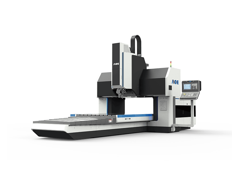
A C-type frame keeps the part close to the column and suits circular parts, small enclosures, cooling plates, motor housings, and wheels, where a C-axis rotates the workpiece through a full revolution. Gantry platforms put the head on a bridge over a fixed table and suit long panels and stiff structures. A 3D head with plus or minus 100 degrees on the A axis and full rotation on C handles curved shells and complex surfaces.
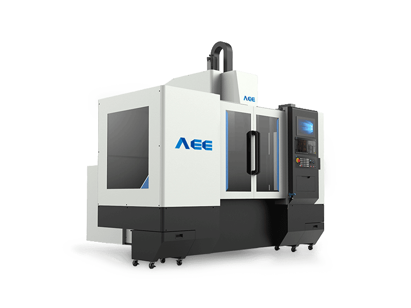
Worktable size is the specification buyers most often underestimate. A compact platform with a 600 mm by 1,200 mm table cannot take a 2,000 mm panel regardless of its thickness rating. Check the part against the table, the throat depth, the clamping concept, and the overhead clearance for loading. On a heavy-load gantry, passable height and width between the columns decide whether a fixture and a crane lift can reach the table.
| Machine form | Geometry it serves | Published example figures | Decision it leaves open |
|---|---|---|---|
| Compact C-type | Circular and small 2D parts | 600 mm by 1,200 mm table, 8 mm depth, 10 m/min in X and Y | Whether the part fits inside the throat with its fixture |
| Dual-worktable C-type | High-mix small parts | Two 600 mm by 1,000 mm stations, automatic tool change | Whether two fixtures justify the extra footprint |
| Gantry, 2D | Long panels up to about 3 m | 2,000 mm by 3,000 mm table, 3,000 mm X stroke | Crane access and floor space around the table |
| Gantry, 1D thick plate | Straight seams from 16 to 25 mm | 2,500 mm by 4,000 mm table, 60 kN Z force | Distortion control on long thick seams |
| Extra-length straight profile | Rail and marine profiles up to 16 m | 6,600 mm by 1,200 mm table, 16,000 mm X stroke | Building length, foundation, and part handling |
| 3D five-axis | Curved shells and housings | A axis plus or minus 100 degrees, 20 mm maximum depth | Tool access on concave surfaces and fixture clearance |
What Positioning Accuracy and Repeatability Do Not Prove
Positioning accuracy and repeatability are axis specifications. Accuracy describes how close the commanded position is to the true position; repeatability describes how consistently the axis returns to the same point. Published values in this class of machine typically sit between 0.02 mm and 0.05 mm for both figures.
Neither number describes a weld. Weld quality depends on force stability, tool condition, fixture stiffness, backing support, and thermal growth during the seam. On a machine with a 16 m X stroke, thermal expansion of the part and the machine over that length moves the tool more than 0.03 mm of axis resolution does, which is why temperature compensation and a warm-up routine matter more than the last digit of the accuracy figure.
Ask how the figure was measured: which axis, loaded or unloaded, at what ambient temperature, and whether compensation is applied. Accuracy quoted at rated force is a different claim from accuracy quoted on an unloaded table, and a 200 kN machine is unlikely to hold both.
Then separate machine tolerance from weld tolerance. The weld acceptance criterion should be written on the joint, with a defined measurement method, and the machine accuracy is only one input to it. A machine can hold every axis specification and still produce a seam that fails sectioning if the force control drifts or the backing plate wears.
Tool Interface, Tooling and Changeover as Specifications
The spindle interface is the stiffness link between the machine and the tool, and it is chosen by torque class rather than by preference. Smaller spindles use a BT40 taper, mid-range spindles move to BT50, and the heavy-load heads use BT60 or a flange interface where the tool assembly is larger than a taper can carry.
Tool holders add a second dimension. A BT 40-130 holder lists 105 mm overall length, 62 mm to the reference face, and 55 mm body diameter; the BT 50-112 lists 155 mm, 118 mm, and 70 mm. Those numbers decide how far the tool reaches into a pocket and how much bending moment the assembly carries at force. A long holder on a high-force machine is a deflection path, and the tool has to be designed around it.
Tool families then constrain the machine, not the other way round. A conventional pin tool covers most butt and lap work. A retractable tool needs independent shoulder and pin actuation so the pin can withdraw and the material can fill the exit hole, which means the machine must support that motion in its control and program. A bobbin tool uses two shoulders and needs no backing support, which makes it the practical choice for long hollow profiles, at the cost of through-thickness access. A stationary shoulder tool keeps the shoulder still and rotates only the pin, which lowers heat input and suits thin walls, fillet welds, and low-thermal-conductivity materials. Spot welding tools work without a travelling seam at all.
That last case changes the equipment question, because a local connection does not require a machine with a long stroke.
Lap joints that need only a local connection rather than a continuous seam lead to a different equipment decision. <Refill Friction Stir Spot Welding (RFSSW)> covers refill spot welding, the variant used where a flush, filled spot is required.
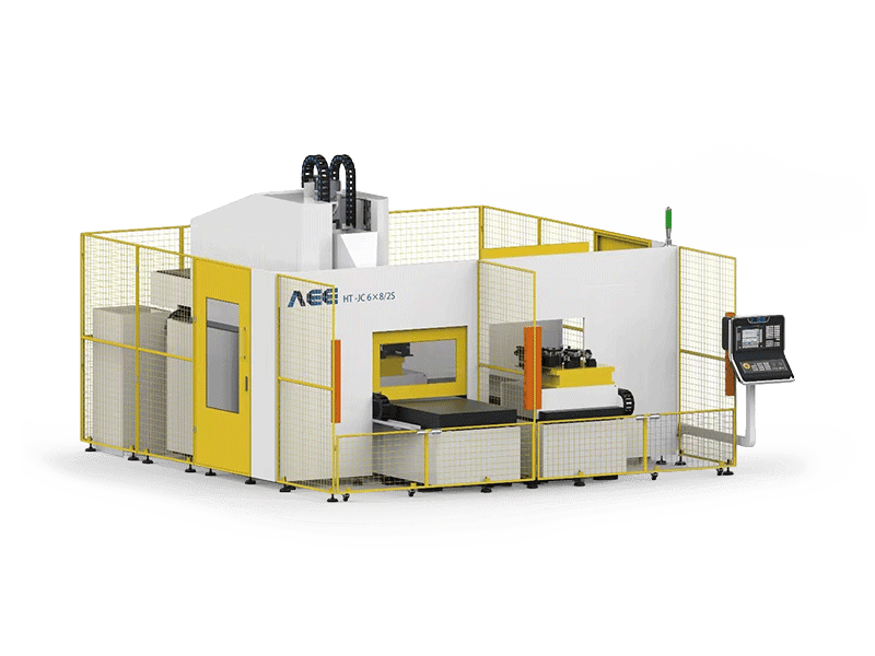
Changeover belongs in the same specification. Ask what the tool change time is, whether it is automatic, how many tools the machine can hold, and how long a fixture change takes. On a dual-worktable platform with 1,200 mm of stroke on each station, welding continues on one table while the other is loaded, which turns changeover from a stopped cost into an overlap. That only helps if the parts are small enough for the stations and the annual volume justifies the second table.
What to Verify Before You Accept the Specification
Every number in a quotation belongs to one of three evidence tiers, and they are not interchangeable.
A catalogue figure is a supplier declaration. It states what the platform is designed to do, in a material and configuration the supplier chose. A factory acceptance record is a measurement on your machine: geometry, axis accuracy, force calibration, spindle runout. A qualified procedure on your part is an applicability result: this alloy, this thickness, this joint, this tool, this parameter set, with a documented outcome.
A sample weld proves less than buyers expect and more than a catalogue does. It covers the alloy, temper, thickness, joint design, tool, fixture, and parameter window tested. It does not transfer automatically to a different heat treatment of the same alloy, a different fixture stiffness, a different operator shift, or a production volume the trial never ran at. Write the trial scope into the acceptance document so the boundary is agreed before the machine ships.
Replace a vague quality requirement with a measurable one before you send the inquiry.
Reject this RFQ line: “Machine must weld 10 mm aluminium with good quality.”
Replace it with: “Single-side full penetration butt weld in 6082-T6, 10 mm, 1,200 mm seam, force-controlled within a declared repeatability, welded with the tool supplied, procedure qualified to the framework named in the contract, weld sectioned and tested against the agreed acceptance criteria.”
Documentation follows the same logic. Ask for the welding procedure specification and its qualification record, the machine acceptance test report, and the CE and ISO 9001 certificates. The certificates cover machine safety and quality management; they say nothing about weld acceptance, and a quotation that offers them as weld evidence is answering a different question.
| RFQ field | What to state | Why it changes the purchase |
|---|---|---|
| Part and alloy | Alloy and temper, thickness range, joint type, smallest and largest production part | A machine sized to the largest part may not weld the thin end with the same spindle |
| Weld length and geometry | Seam length, straight or curved, open or closed contour, seams per part | Sets stroke, welding dimension, and whether a retractable tool is required |
| Force and accuracy requirement | Required axial force window, weld tolerance, and the test that defines acceptance | Separates a machine specification from a weld acceptance criterion |
| Fixture and access | Clamping concept, backing plate, overhead clearance, loading direction | Decides table size, throat depth, and whether a C-frame or gantry fits |
| Tooling and changeover | Tool families, interface type, tool change time, spare holders | Tool cost per metre and changeover time usually dominate running cost |
| Evidence and qualification | Sample weld record, procedure qualification basis, acceptance test report, certificates | Shows what the supplier can prove before shipment and what remains your duty |
Send Your Part Details for a Specification Review
Tell us the alloy and temper, the thickness range, the joint type, the seam length and geometry, the required axial force window, your weld acceptance method, the fixture concept, the annual volume, and the building constraints you are working within. With those fields we can map the part to a platform class, name the spindle and tool interface it needs, and set out what a sample weld would and would not cover before you commit to a purchase.
Dr. Wang Wei, Aerospace Engineering Equipment (Suzhou) Co., Ltd., [email protected], +86 18325808715.
FAQ
What welding thickness should I specify for an FSW machine?
Specify it from the part, not from the largest number available: single-side penetration on the thickest production joint, with the alloy and joint type named. Machine classes move in bands, and the force and torque figures rise with them, from 30 kN and 112 Nm at the 8 mm end to 200 kN and 872 Nm at the 100 mm end. One band above your current part is reasonable when a defined future programme exists. Two bands above, with no part to weld, adds footprint, tooling cost, and complexity you will carry for years.
Is higher spindle rotation speed better for friction stir welding?
No. Rotation speed trades against torque and tool size. Thin sheet uses small tools, higher rotation, and lower force; thick plate uses larger tools, lower rotation, and higher torque. A 1 to 8 mm class spindle publishes 4,000 rpm and 112 Nm, while a 2 to 100 mm class publishes 1,000 rpm and 872 Nm. Match the spindle to the thickness band and alloy, and ask whether the quoted rating is continuous or peak, because a peak figure cannot run a production shift.
Do I need force control or position control?
Force control suits parts whose thickness, flatness, or fixture stiffness varies, including extrusions, castings, and long panels. Position control suits repeatable machined plate on rigid fixtures with a stable thermal environment. Many production machines offer both and switch within a cycle, so the more useful questions are where force is measured, what the stated force repeatability is, and whether force, torque, and temperature are logged per weld. That log is what makes a setting reproducible months later.
What floor space and foundation does an FSW machine need?
Published dimensions scale with force capacity. A compact 8 mm C-type lists roughly 3,050 mm by 2,900 mm and 6,000 kg, while a 100 mm heavy-load gantry lists about 25,000 mm by 8,000 mm and 120,000 kg. Foundation design is a civil engineering decision for your building, so request the machine mass, the force path, and the leveling requirements, then have them checked against the slab and the crane capacity before the layout is fixed.
Can one machine weld aluminium and copper?
Sometimes, within limits. A heavy-load platform can publish 100 mm for aluminium on one side and 35 mm for copper on one side, but copper needs different tools, a different parameter set, and more force relative to thickness. Dissimilar aluminium-to-copper joints add intermetallic control at the interface, which is a procedure question rather than a machine question. Ask for a sample weld on both materials, with the tool and parameters named, before accepting a dual-material claim.
If you’re interested, check out these related articles:
Refill Friction Stir Spot Welding (RFSSW)
AEE provides customer with optional features FSW tool
AEE attend 13th International Symposium on FSW in Kyoto, Japan on 21 – 23 May 2024