
Friction Stir Welding in Power Electronics: IGBT Cooling & Heat Sink Welding
Table of Contents
- Why IGBT Cooling Leaves Little Room for Welding Defects
- How Friction Stir Welding Works for Cooling Plates
- Material Selection for Power Electronics FSW
- Typical IGBT Cooling Plate Configurations
- Process Qualification for Power Electronics Welding
- Machine Selection for Heat Sink and Cold Plate Production
- Tooling for Power Electronics FSW
- From Feasibility Sample to Production Process
- Quality Control and Failure Prevention
- FSW Compared with Brazing, Adhesive Bonding, and Fusion Welding
- Scaling IGBT Cold Plate Welding for Production
- Plan Your IGBT Heat Sink Welding Process
- FAQ
- What makes FSW suitable for IGBT heat sinks?
- Can FSW weld copper heat sinks for IGBT modules?
- What leak rate can an FSW liquid cold plate achieve?
- How do you qualify FSW for power electronics production?
- What plate sizes can be friction stir welded?
- Does FSW require post-weld machining for flatness?
- References
Power electronics thermal design has moved decisively toward liquid cooling for IGBT modules, inverters, converters, and electric-vehicle traction applications. A cold plate or heat sink in these systems does more than remove heat: it must remain leak-tight through repeated thermal cycles, hold flatness after manufacturing, resist corrosion, and avoid introducing contamination into the coolant loop. Friction stir welding has become a practical joining route for these aluminum and copper components because it produces solid-state, low-distortion, repeatable welds without filler, flux, or through-thickness melting [1]. This article explains where FSW fits in IGBT cooling, which cold plate configurations are weldable, how process qualification works, and what makes a heat sink welding process production-ready.
Why IGBT Cooling Leaves Little Room for Welding Defects
An IGBT module transfers heat from the semiconductor die through a direct-bonded copper substrate, solder layer, baseplate, thermal interface material, and finally into a heat sink or liquid cold plate. Any void, crack, flatness deviation, or coolant leak directly affects junction temperature and long-term reliability [5]. Thermal interface quality is particularly sensitive to the contact between the module baseplate and the cooling surface.
Liquid-cooled heat sinks add another layer of difficulty. The welded enclosure must withstand internal pressure, thermal expansion, coolant chemistry, and mechanical assembly loads. Requirements commonly include:
- Low leak rate verified by helium mass spectrometry or pressure decay
- No flux residue, oxide particles, or loose material inside the coolant channels
- Controlled distortion and flatness after welding
- Repeatable joint quality across large production batches
- Full-length root fusion without lack-of-penetration or tunnel defects
These requirements make fusion welding and brazing difficult for many cold plate designs. Fusion processes can create hot cracks, porosity, distortion, and filler-related contamination. FSW reduces these risks because joining occurs below the melting point [1].
How Friction Stir Welding Works for Cooling Plates
FSW uses a rotating, non-consumable tool that plunges into the joint line and moves along the interface between the cover plate and the channel body. Frictional heating plasticizes the material while the tool mechanically stirs and forges the joint closed. Because the material never melts, the process avoids solidification defects such as porosity and hot cracking [2].
For a typical aluminum liquid cold plate, the weld path joins a flat top cover to a machined or extruded channel plate. The rotating shoulder generates most of the heat while the pin stirs through the joint. The result is a continuous solid-state bond across the seam. The low heat input compared with fusion welding reduces distortion and preserves the flatness that power module assembly requires.
The process is also cleaner. No flux, shielding gas, or filler metal is needed, which reduces the contamination risk in internal coolant channels. This is a critical advantage for IGBT cooling circuits where channel cleanliness matters as much as weld strength.
Material Selection for Power Electronics FSW
Aluminum alloys are the most common base material for IGBT heat sinks and liquid cold plates. Extruded 6xxx series alloys such as 6060, 6063, and 6061 are widely used because they combine good thermal conductivity, machinability, corrosion resistance, and extrudability [1]. 5xxx series alloys can be used where higher corrosion resistance or formability is required.
Copper heat sinks and copper inserts are also weldable by FSW, but they demand higher spindle torque, more rigid fixturing, and tool materials capable of operating at higher temperatures. Copper-to-aluminum transition joints are occasionally required for busbar interfaces or for attaching copper cold plates to aluminum manifolds. These dissimilar joints require careful control of intermetallic formation and benefit from co-engineered process development.
Aluminum-to-copper interfaces are among the most demanding thermal-management joints because of intermetallic-layer control and thermal-expansion mismatch. <Customized Dissimilar Material Welding Manufacturers in China> covers co-engineered dissimilar FSW process development for production applications.
In production, the material condition should be part of the initial feasibility study. Heat-treatable 6xxx alloys may be welded in the T4 condition and aged after welding, or welded in T6 with a small reduction in heat-affected zone strength accepted through joint design and qualification testing.
Typical IGBT Cooling Plate Configurations
FSW is used on several heat sink and cold plate configurations in power electronics:
- Flat cover welded to a channel body: The most common configuration. A flat aluminum cover is FSW-welded around the perimeter of a machined or extruded channel plate to form a sealed liquid cavity.
- Double-sided cooling plates: Two covers are welded to opposite faces of a central finned or channel plate, creating a compact cold plate for high-power modules.
- Pin-fin and skived-fin heat sinks: A finned base is sealed with a thin cover to contain coolant flow. This design is common in high-performance IGBT cooling.
- Embedded tube-to-plate joints: Where a copper or stainless steel tube is embedded in an aluminum spreader plate, FSW can join the surrounding aluminum components without the furnace cycle of brazing.
- Closed-loop and circular weld paths: Cooling channels may require closed perimeter welds with no exit hole. Retractable-pin FSW can eliminate the keyhole at the weld end.
Each configuration has different clamping, backing, and tool path requirements. The joint design must allow tool access without crushing thin channel walls or distorting internal fins.
Process Qualification for Power Electronics Welding
FSW in power electronics should be qualified through a formal welding procedure specification, procedure qualification record, and production inspection plan. Internationally, ISO 25239 provides requirements for friction stir welding of aluminum components [1][3]. For aerospace-grade power electronics or demanding inverter applications, AWS D17.3/D17.3M is often used as the qualification framework [4].
A typical qualification program includes:
- Macro-section inspection of the weld nugget, TMAZ, and HAZ
- Tensile and bend testing where standardized specimens can be extracted
- Leak testing by helium mass spectrometer or pressure decay
- Pressure cycling or burst testing for sealed assemblies
- Dimensional and flatness measurement after welding
- X-ray or computed tomography inspection for internal voids and lack of fill
Process monitoring matters as much as the qualification coupon. Production FSW machines should record spindle speed, travel speed, axial force, torque, and weld depth for every part. This data supports traceability and helps detect process drift before a defective lot is produced [3].
Machine Selection for Heat Sink and Cold Plate Production
The right machine depends on plate size, weld depth, production volume, and automation level.
Compact C-type FSW machines are suitable for small radiators, water cooling plates, and power electronics enclosures. They provide a small footprint, high rigidity, and good axis accuracy for short linear welds. Machines in this class are widely used in electronics, communication, and 3C thermal component manufacturing.
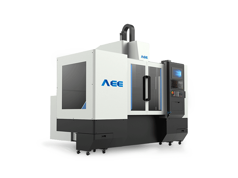
Dual-worktable C-type FSW machines add a second work zone so loading and unloading occur while welding continues. This increases machine utilization and unit throughput. The configuration is especially useful for high-volume IGBT cold plates where multiple parts must be processed per hour. Automatic tool changing and force-position-torque-temperature control also improve repeatability.
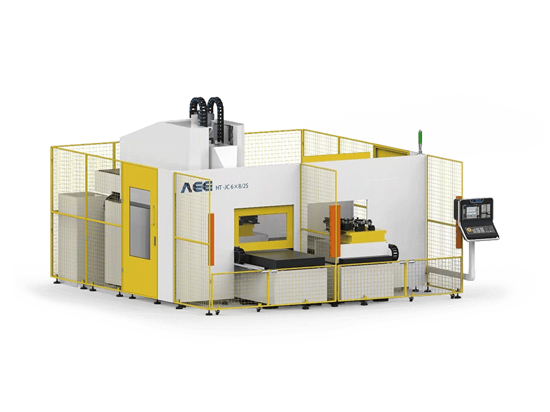
Gantry FSW machines are used for larger cold plates, multi-part fixtures, and long weld paths in power electronics, battery thermal systems, and stationary energy storage. Their larger work envelopes allow multiple cooling plates to be welded in one clamping operation.
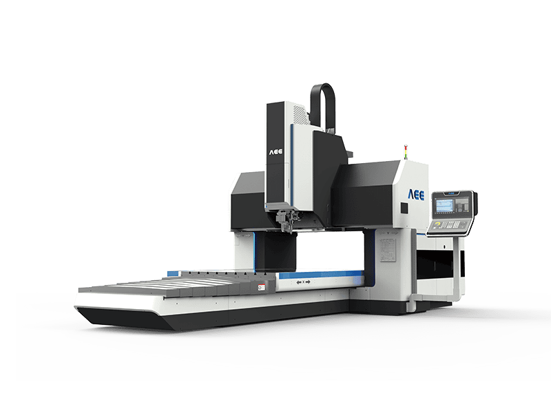
Heavy-load FSW machines are needed for thick copper cold plates, large busbar assemblies, or single-sided welding of thick aluminum thermal plates. 3D FSW machines can weld curved or complex-surface components where the weld path is not planar.
The machine must also be matched to the fixturing strategy. Cold plates require uniform clamping pressure, thermal backing, and weld-path support to prevent channel collapse or root opening. A production fixture should provide repeatable positioning, thermal management, and access for tool entry and exit.
Tooling for Power Electronics FSW
Tool selection is one of the most important decisions in an IGBT heat sink welding program.
Conventional FSW tools are versatile and suitable for perimeter welds, linear cover welds, and most standard aluminum cold plate joints. They deliver stable performance across aluminum, magnesium, and copper alloys in high-volume production.
Stationary shoulder FSW tools separate the shoulder from the rotating pin, which reduces heat input, minimizes flash, and improves surface finish. This tool type is particularly useful for thin-wall cold plates and applications where post-weld surface quality is critical.
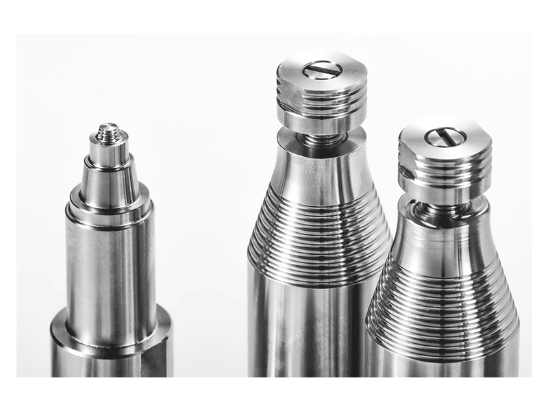
Retractable-pin FSW tools are used when the weld path forms a closed loop. The pin is gradually withdrawn at the end of the weld so the plasticized material fills the exit hole. This is essential for circular cooling channels and closed-contour cold plate designs where a keyhole would create a leak path.
For closed-loop cooling circuits, exit-hole elimination can be a design requirement. <AEE provides customer with optional features FSW tool> covers optional tool features for production welding.
The selected tool material and geometry must be matched to the alloy, plate thickness, and required weld depth. Tool life and replacement strategy should be included in the total cost model because tooling is a consumable in FSW.
From Feasibility Sample to Production Process
A practical development path starts with weld coupons and a representative cold plate sample. The goal is to prove that the joint design can meet both mechanical and leak-tightness requirements before the production line is specified.
For a process feasibility check, send plate drawings, material specification, channel cross-section, and target cycle time to the engineering team. A sample welding plan should include tool selection, fixturing concept, process window, and NDT acceptance criteria. This step reduces risk before equipment investment and identifies whether the design needs changes for tool access, clamping, or weld length.
Contact [email protected] with your cold plate geometry and alloy specification for a feasibility review and sample welding recommendation.
Quality Control and Failure Prevention
A robust IGBT cold plate welding process includes both in-process monitoring and post-weld inspection. In-process monitoring should verify that the machine maintains the approved spindle speed, travel speed, axial force, and torque envelope. Out-of-tolerance events should be recorded and tied to the specific part serial number [3].
Post-weld inspection typically combines:
- Visual and dimensional inspection for flash, surface defects, and flatness
- Helium leak testing or pressure decay testing
- X-ray or CT inspection for internal voids, tunnel defects, and incomplete root penetration
- Macro-section evaluation during process validation
- Periodic tensile and bend testing according to the approved WPS
Flatness requires special attention. Even low-distortion FSW can produce small residual stress gradients across a large plate. Depending on the thermal interface specification, the cover surface may require post-weld machining, stress relief, or flatness correction. The process should be designed so that final machining is stable and repeatable.
FSW Compared with Brazing, Adhesive Bonding, and Fusion Welding
Each joining method has different failure modes in power electronics cooling components.
Brazing can produce strong sealed joints, but it requires furnace cycles, flux or controlled-atmosphere processing, and careful thermal management of large assemblies. It can also leave residual flux contamination if cleaning is insufficient.
Adhesive bonding can be effective for low-pressure applications, but long-term coolant exposure, thermal cycling, and pressure resistance can limit reliability in high-power modules.
Fusion welding of 6xxx aluminum is possible but carries risks of hot cracking, porosity, distortion, and filler-related contamination. The high heat input can also warp thin cold plate covers.
FSW offers a useful middle ground: solid-state bonding without filler or flux, lower distortion than many fusion processes, and excellent repeatability once the process window is established [1][2]. It is not a universal solution. Very small internal channels, extremely thin covers, or designs with no tool-access allowance can make FSW difficult and may require redesign or a different joining method. The decision should be based on joint geometry, material combination, leak-rate target, and production volume.
Scaling IGBT Cold Plate Welding for Production
For series production, the FSW cell should be designed around the part flow, not just the machine. Dual-worktable machines, automated loading, laser weld tracking, and in-process data logging all contribute to stable output. Tool life monitoring and scheduled tool changes prevent process drift.
A production-scale IGBT cold plate line should also include leak testing and dimensional inspection integrated into the same cell. This prevents defective parts from reaching module assembly and provides traceability from weld start to final inspection.
Plan Your IGBT Heat Sink Welding Process
Send your cold plate drawings, alloy specification, leak-rate requirement, and production target to [email protected] or call +86 18325808715. A feasibility review can define the recommended weld joint design, tool type, process window, and inspection plan before equipment investment.
FAQ
What makes FSW suitable for IGBT heat sinks?
FSW creates a solid-state joint without melting the aluminum, which reduces porosity, hot cracking, flux contamination, and distortion. This helps produce sealed cold plates with controlled flatness and clean internal coolant channels [1][2].
Can FSW weld copper heat sinks for IGBT modules?
Yes, FSW can weld copper cold plates and copper-to-aluminum transition joints, but copper requires higher spindle torque, more rigid fixturing, and appropriate high-temperature tool materials. Dissimilar copper-aluminum joints require careful process development to control intermetallic formation.
What leak rate can an FSW liquid cold plate achieve?
The achievable leak rate depends on joint design, process control, and inspection method. FSW cold plates for power electronics are typically verified by helium leak testing or pressure decay, with acceptance limits set by the application specification rather than by the welding process alone.
How do you qualify FSW for power electronics production?
Qualification normally includes a welding procedure specification based on ISO 25239 or AWS D17.3, a procedure qualification record, macro sections, mechanical testing, leak testing, and pressure cycling. Production parts should also have in-process monitoring and periodic inspection [3][4].
What plate sizes can be friction stir welded?
Small IGBT cold plates can be welded on compact C-type machines, while larger heat sinks and multi-part fixtures can be processed on gantry FSW machines. Machine working envelope, clamping strategy, and weld depth determine the practical maximum plate size.
Does FSW require post-weld machining for flatness?
Depending on the thermal interface flatness specification, the cover surface may require post-weld machining or flatness correction. FSW produces lower distortion than many fusion processes, but any residual stress or weld-path variation should be accounted for in the final machining allowance.
References
[1] ISO 25239-1:2020, Friction stir welding — Aluminium — Part 1: Vocabulary, International Organization for Standardization, Geneva, Switzerland.
[2] R. S. Mishra and Z. Y. Ma, “Friction stir welding and processing,” Materials Science and Engineering: R: Reports, vol. 50, no. 1–2, pp. 1–78, 2005.
[3] ISO 25239-5:2020, Friction stir welding — Aluminium — Part 5: Quality and inspection requirements, International Organization for Standardization, Geneva, Switzerland.
[4] AWS D17.3/D17.3M:2016, Specification for Friction Stir Welding of Aluminum Alloys for Aerospace Applications, American Welding Society, Miami, FL, USA.
[5] JEDEC JESD51, Methodology for the Thermal Measurement of Component Packages, JEDEC Solid State Technology Association, Arlington, VA, USA.
If you’re interested, check out these related articles:
AEE provides customer with optional features FSW tool
Customized Dissimilar Material Welding Manufacturers in China
AEE attend 13th International Symposium on FSW in Kyoto, Japan on 21 – 23 May 2024
Refill Friction Stir Spot Welding (RFSSW)