
Friction Stir Welding for Pressure Vessels: Feasibility and Code
Table of Contents
- Why Pressure Vessel Fabricators Consider FSW
- Joint Configurations and Tooling That Decide Feasibility
- Material Behavior: Strength, Distortion, and Residual Stress
- Code Routes and Qualification Requirements
- ASME Section VIII and Section IX Route
- ISO 25239 and AWS D17.3/D17.3M
- Inspecting FSW Pressure Boundaries
- Feasibility Study and Data to Collect
- Where FSW Is Not the Right Choice
- Plan Your Pressure Vessel FSW Qualification
- FAQ
- Is FSW already accepted by ASME pressure vessel codes?
- Does FSW always leave a hole at the weld end?
- How thick can an FSW pressure vessel seam be?
- How do you detect the main FSW defects in a pressure boundary?
- Is FSW cheaper than TIG or MIG for a pressure vessel?
Friction stir welding (FSW) is feasible for many aluminum pressure vessels, but it is not a code shortcut. The process can produce low-porosity, low-distortion seams with a fine recrystallized structure that supports pressure retention and fatigue performance. What makes an FSW joint acceptable as a pressure boundary is not the welding demonstration alone. The design code, inspection plan, closure method, and qualification record must together prove that the seam will remain leak-tight under design pressure, temperature, and service conditions.
The most realistic first applications are aluminum cylindrical shells, flat closures, and enclosed cooling channels where long straight or circular seams can be programmed and clamped. High-strength, crack-sensitive alloys that are difficult to fusion weld are often better candidates for FSW than conventional arc processes, provided the joint design and tooling close the weld path without leaving an exit hole.
Why Pressure Vessel Fabricators Consider FSW
Pressure vessel fabricators usually evaluate FSW when they need to reduce defects that fusion welding can introduce. Porosity, solidification cracking, filler chemistry mismatch, and excessive distortion are common concerns in aluminum pressure boundaries. FSW avoids melting the base metal. A rotating tool plasticizes and forges the material below the melting point, which reduces gross porosity and hot-crack risk while creating a refined weld nugget.
The main trade-off is process force. FSW requires a rigid machine, strong fixturing, and close control of plunge depth, tool tilt, rotation speed, and travel speed. A successful weld depends on maintaining forging pressure along the full seam. That makes FSW best suited to programmed seams with consistent thickness and accessible clamping, not highly variable manual repairs.
For pressure vessels, the benefit is not simply higher tensile strength. It is the combination of reduced distortion, fewer volumetric defects, lower residual stress in many cases, and better repeatability on long production seams.
Joint Configurations and Tooling That Decide Feasibility
Pressure vessel FSW usually involves two closure types: a straight longitudinal seam and a circular girth seam. Each has a different closure risk.
A conventional FSW tool leaves an exit keyhole when the pin withdraws. In a pressure boundary, that hole is unacceptable. A design can move the keyhole into a sacrificial runoff tab that is machined away after welding, or it can use a retractable pin tool. The retractable pin design withdraws the pin into the shoulder while the plasticized material around it refills the cavity, eliminating the final hole.
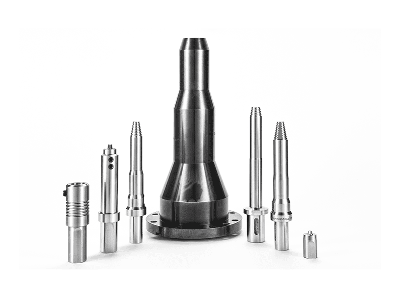
For closed cylindrical shells, circular seams, and applications that cannot tolerate an exit hole, the retractable pin is usually the first tooling choice. It adds machine control requirements because the shoulder and pin move independently during weld termination.
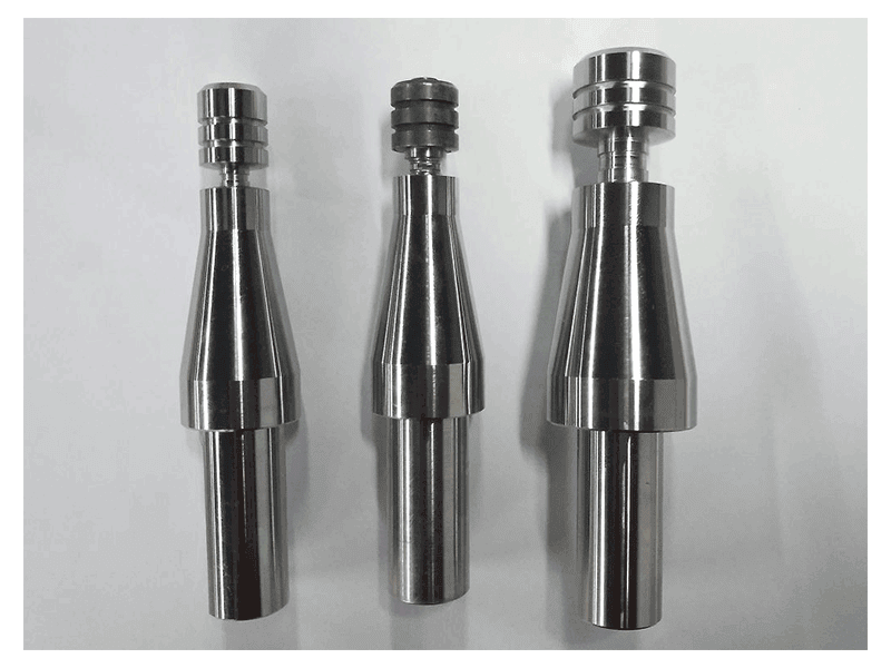
Longitudinal seams in hollow profiles and barrel sections present a different issue: access to the root side for a backing bar. A bobbin tool supports the seam with shoulders on both sides of the workpiece, so the weld is self-reacting and does not require a rigid anvil behind the joint.
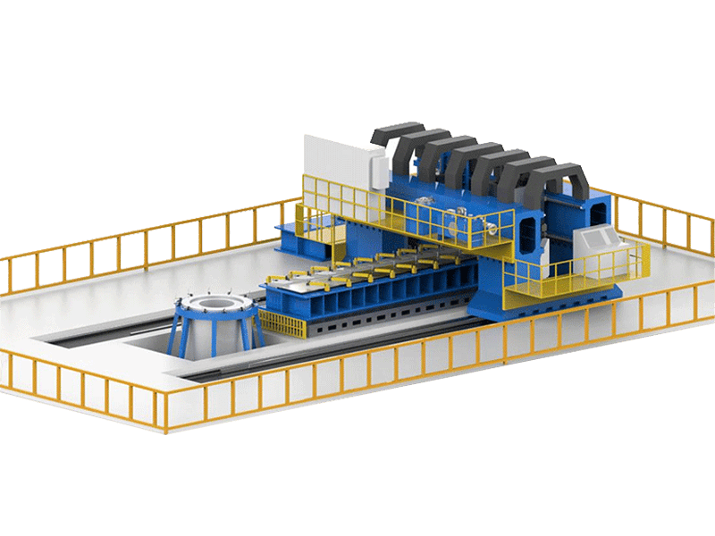
Equipment selection follows the joint configuration. Thick aluminum shells, long circumferential seams, and high-production girth welding require machines with high torque, high axial load capacity, and stable rotational precision.
The table below compares closure options for pressure vessel seams.
| Closure method | Typical use | Pressure-boundary requirement |
|---|---|---|
| Conventional pin with runoff tab | Straight seams with sacrificial material at the ends | Keyhole must be removed outside the final pressure boundary |
| Retractable pin | Circular girth seams and closed paths | Pin retraction must fill the exit hole reproducibly |
| Bobbin tool | Long straight hollow profiles and barrel seams | Root side is forged without a rigid backing bar |
| Stationary shoulder | Thin-wall shells and low-distortion surfaces | Lower heat input but not a keyhole-closure solution by itself |
Material Behavior: Strength, Distortion, and Residual Stress
FSW creates a characteristic weld zone with a stir zone, thermomechanically affected zone, and heat-affected zone. In 5xxx aluminum alloys such as 5083 and 5086, the non-heat-treatable structure retains much of its useful strength and corrosion resistance after welding. In 6xxx alloys such as 6061, the heat-affected zone still softens, so the design allowable may be lower than the unwelded base metal even though the weld is sound.
The process does not erase heat-affected-zone considerations. It changes where the loss occurs and often reduces the width of heavily affected material. For pressure design, the critical questions are not only joint strength but also long-term fatigue behavior, stress corrosion resistance, and whether the chosen temper can meet code allowables at operating temperature.
Distortion is usually lower than fusion welding because heat input is localized, but it is not zero. Large thin shells still need proper sequencing, clamping, and stress relief or straightening depending on the code and design.
Residual stress is also present in FSW. The longitudinal stress profile is often lower than a comparable fusion weld, but tensile residual stress near the seam can remain. If the vessel enters aggressive service, the design should account for residual stress rather than assume FSW has completely relaxed the joint.
Code Routes and Qualification Requirements
FSW is not normally a prequalified welding process under major pressure vessel codes. It therefore requires a procedure qualification route supported by mechanical testing, destructive examination, non-destructive testing, and a final pressure test.
ASME Section VIII and Section IX Route
In an ASME Section VIII project, the manufacturer must qualify the welding procedure through the applicable Section IX requirements. That usually includes tensile tests, bend tests where practical, macro examination, and radiography or other specified NDT. Because FSW is a less familiar process to many inspection authorities, the designer, manufacturer, and Authorized Inspector may agree on supplemental demonstration requirements such as additional macro sections, leak tests, or fatigue samples.
Qualification proves that a specific WPS can produce acceptable joints with a defined machine, tool type, material thickness range, and parameter window. It does not by itself grant product approval.
ISO 25239 and AWS D17.3/D17.3M
The ISO 25239 series is the main published reference for friction stir welding of aluminum. It covers terminology, joint design, operator qualification, welding procedure specification and qualification, and inspection requirements. Even when a pressure vessel code does not incorporate ISO 25239 directly, the series provides a practical framework for controlling FSW quality.
AWS D17.3/D17.3M is used for friction stir welding of aluminum alloys in aerospace applications. It may be referenced as a supplementary acceptance basis for high-reliability seams, but it does not replace the governing pressure vessel code.
In Europe, a manufacturer may use FSW within the Pressure Equipment Directive framework when the conformity assessment demonstrates that the fabrication route, material properties, test results, and inspection plan satisfy the essential safety requirements. A Notified Body often reviews the qualification and final inspection plan.
Inspecting FSW Pressure Boundaries
FSW reduces many fusion-weld discontinuities, but it introduces its own failure modes. The most important are planar or root-related flaws that cannot be accepted as pressure-tight by visual inspection alone.
| Discontinuity | Typical origin | Pressure-boundary effect | Useful detection |
|---|---|---|---|
| Tunnel or wormhole | Low heat input, improper flow, wrong travel speed | Continuous leak path or stress concentration | Radiography, phased-array UT |
| Incomplete penetration | Short pin, poor root support, incorrect plunge | Root leak and reduced section | Phased-array UT, macro section |
| Kissing bond | Oxide entrainment or insufficient forging at the interface | Weak planar defect, may leak under pressure | High-resolution UT, destructive macro |
| Root concavity | Excessive plunge or tool mismatch | Local thinning | Visual, gauging, UT |
| Hook or cold lap | Lap-joint interface folding in nozzle or fitting areas | Leak path and reduced load area | Macro section, phased-array UT |
| Exit-hole defect | Conventional pin withdrawal without refilling | Direct leak path | Visual, penetrant, pressure test |
Phased-array ultrasonic testing is often the most capable method for planar FSW defects, but it must be qualified on representative FSW samples. Radiography is useful for volumetric tunnels and gross internal channels but can miss tight kissing bonds. For this reason, destructive macro examination during qualification is indispensable. The production pressure test demonstrates that a completed vessel holds pressure, but it does not eliminate the need for NDT aimed at planar defects.
Feasibility Study and Data to Collect
Before committing to an FSW pressure vessel program, a practical feasibility study should weld representative production sections and then section them across the seam. The study should verify full root penetration, weld surface quality, flash, thinning, and the absence of the defects listed above.
This is the point to compare the weld record with the proposed design allowables, not just to confirm that the plate is stuck together. A supplier cannot responsibly promise pressure-code acceptance from a beautiful weld photograph. The data must show that the seam can be made repeatedly within the required parameter window and inspected to a defined acceptance limit.
The table below can be used to structure a request for quote and feasibility welding.
| Information requested | Why it matters for FSW |
|---|---|
| Alloy and temper | Determines tool material, heat-input limits, and allowable properties |
| Minimum and maximum wall thickness | Sets pin length, shoulder diameter, machine force, and backing method |
| Joint type and seam length | Determines longitudinal, girth, or closed-path strategy |
| Design code and service conditions | Defines qualification, NDT, and final acceptance route |
| Production volume and cycle time | Justifies manual, semi-automatic, or full production line configuration |
| Required NDT and surface finish | Controls tool selection, clamping, and post-weld processing |
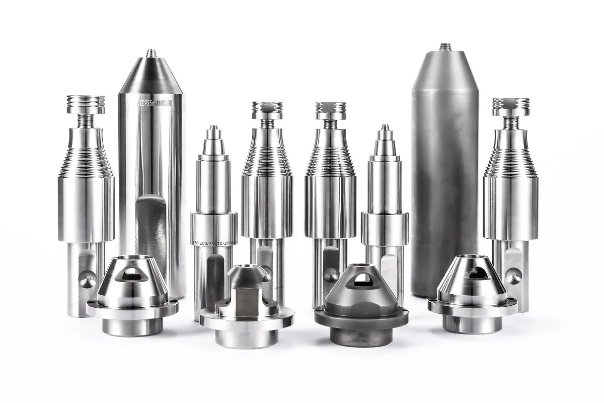
A practical study should also include a pressure test or leak test on a representative closure. That test confirms not only the weld path but also the exit-hole elimination method and the final machined condition.
Where FSW Is Not the Right Choice
FSW is not ideal when the joint cannot be rigidly supported or when the weld path includes tight internal corners, complex nozzle transitions, or short repeated attachments better made by qualified manual fusion welding. Steel pressure vessels are also more difficult for FSW because tool wear, process temperature, and equipment force requirements escalate rapidly.
Very low-volume one-off vessels may not justify the fixture and qualification investment unless FSW solves a specific fusion problem such as crack-sensitive aluminum, a leak-prone long seam, or an assembly where distortion cannot be tolerated. A one-time repair on an existing vessel is rarely a good FSW application unless the original vessel was designed for the process and the repair can be supported from both sides.
Plan Your Pressure Vessel FSW Qualification
The practical way to start is a sample-welding program on production-representative material. Send Aerospace Engineering Equipment (Suzhou) Co., Ltd. the alloy and temper, wall thickness range, shell diameter, joint type, design code, operating pressure and temperature, service fluid, NDT requirements, and estimated production volume. AEE can then propose the appropriate machine, tool type, fixturing, and qualification plan before investment.
For technical evaluation, sample welding, or machine selection, contact AEE at [email protected] or +86 18325808715.
FAQ
Is FSW already accepted by ASME pressure vessel codes?
FSW is not a conventional prequalified process under ASME Section VIII. It can be qualified through the applicable Section IX procedure route, supplemented by destructive testing, appropriate NDT, and agreement with the Authorized Inspector. Acceptance depends on the specific WPS, not on FSW as a category.
Does FSW always leave a hole at the weld end?
A conventional FSW tool leaves an exit keyhole unless the design moves the keyhole into sacrificial material or uses a retractable pin tool. For pressure vessels, the keyhole must be eliminated, usually by machining away a runoff tab or by using a retractable pin that refills the cavity during withdrawal.
How thick can an FSW pressure vessel seam be?
Feasibility depends on the alloy, machine force, tool geometry, and required inspection. Thin aluminum shells, commonly a few millimeters up to around 30 mm, are realistic production targets. Thicker sections require larger high-torque equipment, stronger fixturing, and more demanding NDT qualification.
How do you detect the main FSW defects in a pressure boundary?
Phased-array ultrasonic testing is often the most useful production method for planar defects such as lack of penetration, kissing bonds, and tunnel flaws. Radiography can detect volumetric tunnels but may miss tight interface defects. Destructive macro sections during qualification are essential to confirm root penetration and closure quality.
Is FSW cheaper than TIG or MIG for a pressure vessel?
It can be when the application includes crack-sensitive aluminum, long repeated seams, high leak-test demand, or distortion control. The initial machine, fixture, and qualification cost is higher. The economic case usually comes from reduced rework, less filler material, fewer weld defects, and a more repeatable automated process.
If you’re interested, check out these related articles:
AEE attend 13th International Symposium on FSW in Kyoto, Japan on 21 – 23 May 2024
Customized Dissimilar Material Welding Manufacturers in China
Refill Friction Stir Spot Welding (RFSSW)