
Friction Stir Welding for Military Vehicle Applications
Table of Contents
- Why Friction Stir Welding Fits Military Vehicle Structures
- Materials and Joints That Military Vehicles Typically Combine
- Process Control, Distortion and Joint Performance
- Machine Selection for Defense Programs
- Qualification and Inspection Evidence
- From Prototype to Production
- Planning a Defense FSW Program
- Frequently Asked Questions
- Can FSW weld 7xxx series aluminum armor?
- What thickness range is practical for military vehicle FSW?
- Does FSW need a backing plate for every military part?
- How is FSW validated for defense applications?
Friction stir welding for military vehicle applications is a solid-state joining route that can produce strong, repeatable aluminum joints without melting the parent material. That is valuable in hull panels, structural frames and weight-sensitive assemblies where distortion, hot cracking and porosity create qualification risk in fusion welding. The practical challenge for a defense program is not deciding whether FSW works in principle. It is defining the alloy stack, joint access, machine capability, process window and inspection evidence that will support the specific vehicle requirement. This article addresses those decisions from a manufacturing and process qualification perspective rather than treating FSW as a simple substitute for conventional welding.
Why Friction Stir Welding Fits Military Vehicle Structures
FSW forms a joint by plunging a rotating tool into the workpieces and moving it along the seam. The material around the tool plasticizes from frictional and deformation heating, but it does not reach the liquidus temperature. Because solidification does not occur in the same way as fusion welding, many of the defects that limit fusion welds in aluminum are avoided. Solidification cracking and hydrogen porosity have less opportunity to form, which is particularly useful for 2xxx and 7xxx alloys that are otherwise difficult to join.
For military vehicles, the benefit usually appears as lower distortion and more consistent joint properties across long production runs. Large flat panels, side modules and floor structures can be welded with smaller post-weld correction than would often be required after fusion welding. The process is not universal. Part access, rigid backing and high machine forces still determine whether FSW is practical for a given seam. Closed shapes, sharp contours and areas with no back access may require a different tool or a different joining approach.
Materials and Joints That Military Vehicles Typically Combine
Military vehicle structures often bring together 5xxx plate, 6xxx extrusions and higher-strength 7xxx sections in the same assembly. FSW can join these families, but the alloy family alone does not define the result. Temper, thickness, joint geometry and the required post-weld performance establish the real process limits.
| Material family | Typical vehicle role | FSW consideration |
|---|---|---|
| 5xxx aluminum | Blast-resistant plates and side hull panels | Good general weldability; procedure must preserve the required post-weld strength and ductility |
| 6xxx aluminum | Extruded frames, cover plates and mounting rails | Heat-treatable; thermal input must be balanced against strength loss in the heat-affected zone |
| 7xxx aluminum | High-strength armor and load-bearing sections | Hard to fusion weld; FSW reduces hot-cracking risk but the weld zone still requires mechanical qualification |
| Aluminum to steel | Transition brackets and attachment interfaces | Requires controlled process development; intermetallic formation and property transfer must be verified |
| Magnesium alloy | Lightweight covers and secondary structures | Needs tool material and process limits matched to the alloy |
| Cast aluminum | Housings and end fittings | Parent casting porosity may remain; pre-weld inspection is part of the feasibility decision |
For dissimilar joints, the main discipline is to separate what the metallurgy can support from what the drawing assumes. A lap joint that appears simple may hide hooking, thinning or root defects if the tool path is not matched to the weaker material. When dissimilar combinations are unavoidable, representative sectioning and mechanical tests should be completed before production release.
When the structure mixes aluminum with steel or other metals, the joint design and tool path should be treated as one development task instead of a supplier afterthought. <Customized Dissimilar Material Welding Manufacturers in China> covers how customized FSW development supports difficult material combinations.
Process Control, Distortion and Joint Performance
Rotation speed, travel speed, axial force and tool tilt control the heat and material flow inside the weld. In heat-treatable alloys, too much heat can soften the joint even if the weld surface looks acceptable. Too little heat can leave an unjoined root. A reliable military application therefore needs more than a parameter list. It needs a recorded process window that connects machine feedback to sectioning, tensile and bend results.
Tool geometry is part of the same system. The shoulder provides most of the surface heating and forging, while the pin profile drives vertical material flow. Tool selection should follow the joint configuration, thickness and material stack rather than a general catalogue preference. For thin sections, a stationary shoulder design can reduce surface overheating and improve appearance. For closed contours, a retractable pin tool may be needed to eliminate the exit hole where the specification requires a complete seam.
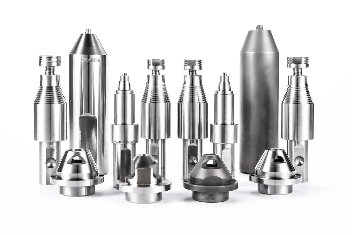
Process monitoring also matters in defense work. Machines that capture force, torque, temperature and position provide a record that can identify drift before an entire lot is affected. The log itself is not proof of joint quality. It becomes useful only when the recorded conditions are correlated with destructive and non-destructive results during qualification.
Machine Selection for Defense Programs
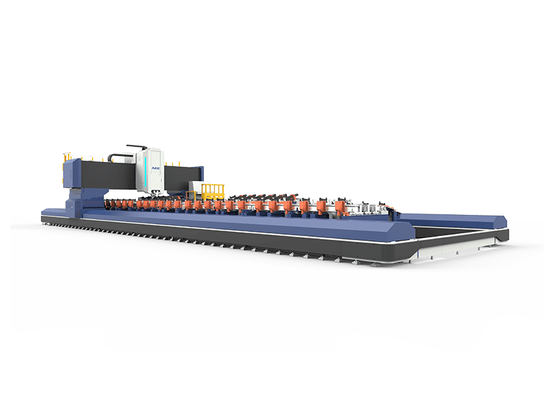
Small covers and brackets may fit a compact C-type machine. Long side profiles and large hull panels require a gantry or extra-length bed. Thick aluminum armor increases the required Z-axis force, and curved panels add rotary-axis demands. The correct starting point is not the largest machine. It is the machine that can hold the part rigidly, control the tool orientation and maintain the required force across every seam.
| Machine type | Defense use | Selection factor |
|---|---|---|
| C-type | Small housings, electronics enclosures and brackets | Throat depth and force capacity must match the part |
| Gantry | Large panels, floor sections and modular hull assemblies | Work envelope and fixture rigidity are usually the limiting constraints |
| Heavy-load | Thick aluminum armor and structural beams | Spindle torque and Z-axis force govern penetration and stability |
| 3D | Curved hull parts and contoured side modules | Rotary axes must maintain the correct tilt and normal force on curved seams |
| Extra-length | Long side rails, roof panels and side profiles | Bed length and straightness control seam alignment over long travel |
A defense program rarely starts with an off-the-shelf configuration. The machine, fixture, spindle and tooling often need to be adapted together, and the clamping plan must stop the part from lifting or moving under forging force.
A defense program rarely starts with an off-the-shelf configuration; the machine, fixture, spindle and tooling usually need to be adapted together. <AEE provides customer with optional features FSW tool> covers the optional tooling and machine features that shape a production FSW cell.
Aerospace Engineering Equipment supplies machine platforms across this range, including heavy-load equipment capable of single-side aluminum depths up to 100 mm and gantry systems for large panels. That capacity is an engineering envelope for feasibility, not an automatic guarantee for every armored assembly. The final capability depends on the alloy, joint design, fixturing and the inspection evidence required by the platform specification.
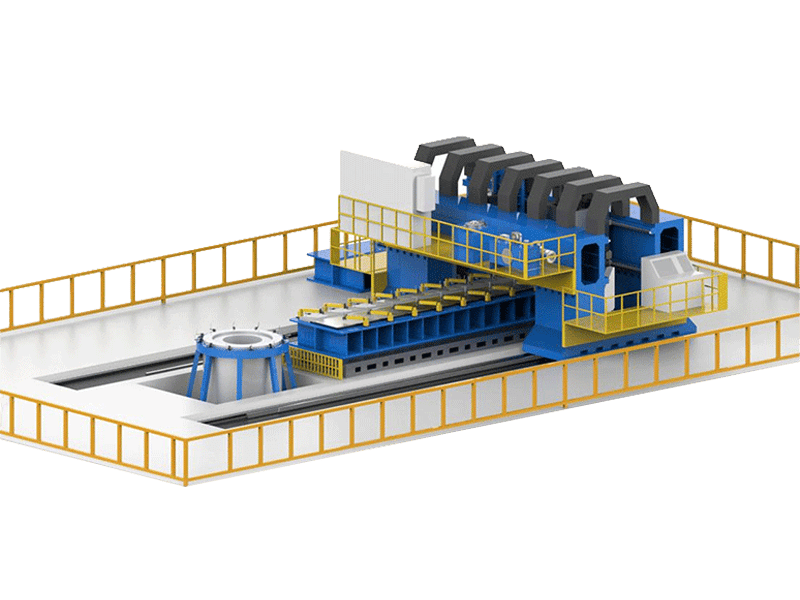
Large hull panels and floor structures test the work envelope in a different way. The gantry bed, clamping system and thermal expansion path must be planned together so that the part does not shift as heat moves through the structure. A long seam that welds acceptably in a short trial may still fail in production because the fixture loses alignment after repeated thermal cycles.
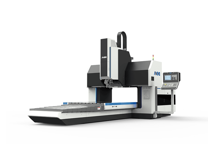
Curved blast panels and contoured side modules add three-dimensional travel and tool orientation requirements. The machine must keep the tool normal to the seam or at the intended tilt angle without losing axial force control. This makes rotary-axis stiffness and path repeatability part of the acceptance review.
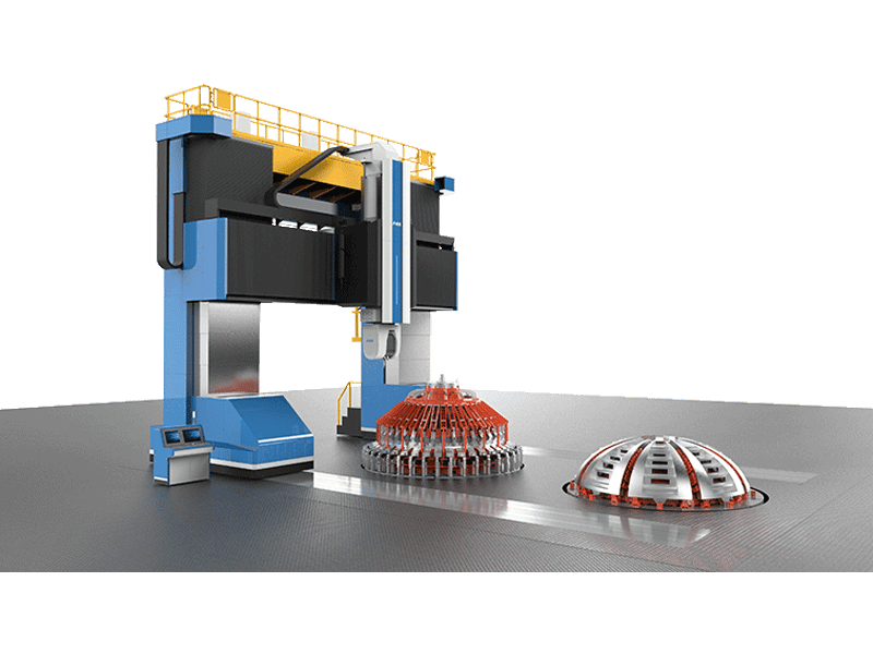
Long extruded profiles create a related alignment problem at extended lengths. Straightness, clamping spacing and sequencing can influence the weld as much as spindle speed. In these applications, the machine travel must remain stable over the full component length rather than only across a short demonstration coupon.
Qualification and Inspection Evidence
Military users rarely accept a weld because it looks continuous. The release package usually combines a qualified welding procedure, process logs, sectioning and NDT evidence. Before production begins, the program should agree on acceptance criteria for root flaws, hooking, flash, voids and surface conditions, because different platform specifications may treat the same indication differently.
| Evidence | What it can show | What it does not establish |
|---|---|---|
| Visual inspection | Surface flash, undercut and gross mismatch | Internal root condition |
| Radiographic or CT inspection | Voids, tunnels and embedded gaps | Fine material flow or heat-affected zone softening |
| Ultrasonic or phased array testing | Planar indications and root geometry | Strength or fatigue life without correlation data |
| Tensile testing | Weld efficiency under laboratory loading | Ballistic performance or full service life |
| Macro sectioning | Nugget shape, root fusion and hooking | Long-run process stability |
| Process logs | Force, torque, temperature and speed | Acceptability unless correlated to destructive tests |
Ballistic qualification is a separate requirement. FSW evidence can support a manufacturing consistency case, but it does not replace armor certification or platform-level survivability testing. When a component has a protection function, the welding program and the ballistic program need to share the same material, joint and heat-treat condition definitions.
From Prototype to Production
Scaling FSW into production should not mean changing every variable at once. A defense component can move from feasibility coupons to representative mock-ups and first article parts while keeping the critical parameters inside the qualified window. Each stage should generate a short record of what changed, what remained constant and which test evidence was collected.
- Confirm the material stack, thickness, joint type and post-weld property targets.
- Produce feasibility welds and section them to check root fusion and nugget shape.
- Lock the parameter window and the fixture configuration that support the required result.
- Validate the production setup with destructive tests and the selected NDT methods.
- Qualify the procedure and train operators on the actual production equipment.
- Scale to the target machine or automated line with process logging and periodic verification.
Automated production lines become useful when the part family, volume and quality record justify fixed tooling and material handling. For lower-volume defense platforms, a flexible machine with repeatable fixturing may be more appropriate than a dedicated line. The decision should follow the production rate and the cost of qualifying each configuration.
Planning a Defense FSW Program
If you are evaluating FSW for a military vehicle component, send the joint stack, material grades, part envelope, production rate and required acceptance evidence. We can review seam access, tooling, machine force and inspection coverage against the actual drawing rather than against a general catalogue capability. For a protection-rated part, include the applicable ballistic or platform qualification requirements so the manufacturing evidence is scoped correctly. Contact Aerospace Engineering Equipment (Suzhou) Co., Ltd. at [email protected] or +86 18325808715.
Frequently Asked Questions
Can FSW weld 7xxx series aluminum armor?
Yes, under controlled conditions. FSW reduces the hot-cracking and porosity mechanisms that make 7xxx alloys difficult to fusion weld, but the heat-affected zone still responds to the thermal cycle. A production answer must come from procedure qualification for the specific temper and thickness, supported by sectioning and mechanical testing. Do not infer full performance from the alloy family alone.
What thickness range is practical for military vehicle FSW?
It depends more on machine force, spindle torque and backing support than on the process itself. Thin sheet requires careful heat control and may benefit from a stationary shoulder tool. Thick sections require a high-force machine, and single-side aluminum welding in the 100 mm range can be supported by heavy-load equipment, but each joint still needs feasibility samples. The final range is defined by the part, not by a single machine number.
Does FSW need a backing plate for every military part?
Most butt joints require a rigid backing or anvil to react the forging force and support the root. Bobbin tools can weld some hollow sections without rigid backing because the probe is supported from both sides, but they do not fit every geometry. The backing material, surface condition and thermal path should be treated as part of the fixture design.
How is FSW validated for defense applications?
Validation usually starts with a written welding procedure and a controlled process record. The evidence package includes macro sections, tensile or bend tests, NDT where required and weld logs correlated to the qualified window. FSW validation demonstrates manufacturing consistency and joint quality. Ballistic qualification remains a separate requirement when the part has a protection function.
If you’re interested, check out these related articles:
AEE attend 13th International Symposium on FSW in Kyoto, Japan on 21 – 23 May 2024
Customized Dissimilar Material Welding Manufacturers in China