
Friction Stir Welding for Bridge and Civil Aluminum Structures
Table of Contents
- Why FSW Suits Long Aluminum Bridge and Civil Structures
- Joint Design and Alloy Selection for Structural Aluminum
- Machine Selection for Long Seams and Thick Bridge Sections
- Backing, Clamping, and Thermal Management
- Qualification and Inspection for Civil Projects
- When FSW Is Not the Right Choice for a Bridge Project
- Feasibility and Supplier Selection Before Buying
- Plan Your First Bridge Panel Feasibility Study
- FAQ
- Can FSW be performed on-site for bridge structures?
- What aluminum alloys are best for bridge and civil FSW?
- How thick can FSW weld an aluminum bridge structure?
- Does FSW meet structural welding codes?
- Why choose FSW over MIG or TIG for bridge deck panels?
Friction stir welding (FSW) has become a practical choice for bridge decks, pedestrian spans, access platforms, and other civil aluminum structures when the components can be welded in a controlled shop environment. It creates a solid-state joint without melting the parent metal. For long extruded profiles and stiffened panels, that means lower distortion, no filler-metal chemistry to control, and a weld that can remain consistent over a seam length of many meters. The process is not a universal replacement for fusion welding. It works well only when the joint design, machine travel, backing, and clamping are planned together. This article follows the decisions a structural fabricator or consulting engineer should make before specifying FSW for a bridge or civil structure.
Why FSW Suits Long Aluminum Bridge and Civil Structures
In FSW, a rotating pin and shoulder generate frictional heat, plasticize the aluminum locally, and forge the material into a joint as the tool moves along the seam. The parent metal does not melt. That single difference changes the manufacturing logic for bridge and civil work. Porosity and hot-cracking risks linked to filler and solidification are avoided. Heat input stays more localized than a typical MIG or TIG weld, which helps maintain flatness on wide deck panels where out-of-plane distortion can create fit-up and drainage problems.
The process also suits the geometry of many civil aluminum components. Multi-void extruded deck sections, side rails, parapet profiles, and stiffened panels often require long straight or gently curved seams. A machine with sufficient travel can weld these without stopping and restarting, so the producer avoids the local discontinuities that can occur at arc starts and stops. Because travel speed, spindle speed, axial force, and tool position are controlled by the machine, the weld record can be made repeatable across production.
That repeatability does not remove the need for process development. The weld path must be straight or within the machine’s controlled curvature, the two sides need enough support to resist forge force, and the joint fit-up must be tighter than the typical tolerance a fabricator might accept for a fusion weld. When those conditions are present, FSW becomes a strong candidate for the primary structural seam.
Joint Design and Alloy Selection for Structural Aluminum
Bridge and civil fabrications usually start with extruded aluminum shapes or rolled plate. The joint is commonly a butt seam between two profiles, a lap seam between a plate and a stiffener, or a closure weld on a hollow profile. FSW is most accessible when the rotating tool can enter from one side and the shoulder can ride on a clean, supported surface. A joint with a large mismatch, an open gap, or an internal cavity directly below the weld line requires a dedicated tool and backing concept.
Alloy selection controls both the structural capacity and the process window. 5xxx work-hardened plate is used where corrosion resistance and weldability matter, but the weld region loses some of the original cold-work strength and must be designed in the as-welded condition. 6xxx extrusion alloys are common for deck planks, rails, and beams because they extrude well and accept FSW reliably, although the heat-treatable condition also softens in the process zone. 7xxx alloys can offer high strength, but their process window is narrower and they require careful evaluation for stress corrosion and qualification requirements. A practical bridge specification usually selects one alloy family and validates the joint in its actual welded condition instead of assuming full base-metal properties.
| Alloy family | Common bridge and civil form | Main FSW consideration |
|---|---|---|
| 5xxx plate | decks, access platforms, marine-influenced structures | design to as-welded strength after cold-work loss |
| 6xxx extrusions | multi-void deck panels, beams, rails | good formability and weldability; allow for process-zone softening |
| 7xxx high-strength | specialty structural members | high strength possible; narrower process window and corrosion qualification |
A supplier should be asked to demonstrate the joint configuration on the specific extruded shape rather than on a generic flat coupon. Wall thickness, internal ribs, and local stiffness all change the heat flow and the resulting weld quality.
Machine Selection for Long Seams and Thick Bridge Sections
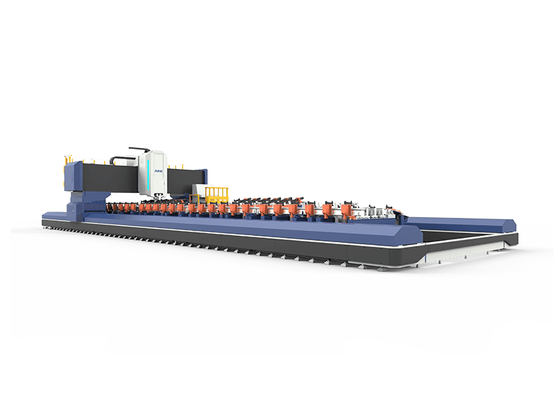
A bridge panel is not a small part. The machine must hold the full workpiece, maintain constant feed and axial force across the weld length, and keep positioning repeatable enough for a straight structural seam. For long thin and medium-thickness profiles, an extra-length straight-profile machine provides the X-axis travel needed to weld the full seam without moving the panel halfway through. Supplied capability in this class includes a 16,000 mm X stroke, an 8 mm maximum welding thickness for 6xxx aluminum, and a 30 kN Z-axis force, which suits long parapet, deck, and side-rail seams.
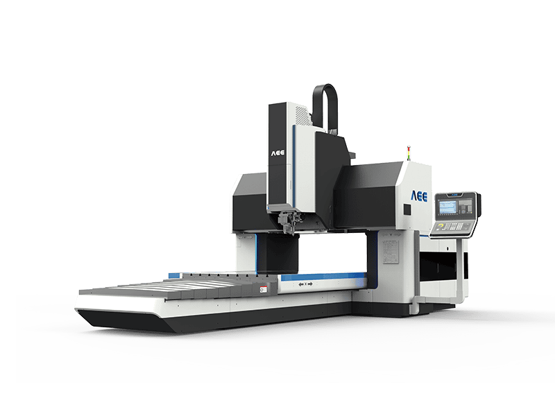
Wider deck panels and plate-stiffened structures are better handled on a gantry machine because the gantry supports the panel across a larger working table and provides higher Z-axis force for thicker material. Supplied gantry data suitable for bridge work includes a 2,500 mm by 4,000 mm table with 25 mm maximum welding thickness and 60 kN of Z-axis force. For thick support ribs, bearing blocks, and high-load connections, a heavy-load machine is required. The supplied heavy-load class reaches 100 mm single-side aluminum welding depth, 190 mm double-side welding depth, and 200 kN of Z-axis force, but the workpiece must fit within its travel and pass height.
The values below come from the product library of Aerospace Engineering Equipment (Suzhou) Co., Ltd. and represent supplied machine capabilities, not universal industry limits.
| Bridge requirement | Preferred machine class | Relevant supplied capability | Selection reason |
|---|---|---|---|
| Long thin extruded deck or side-rail seams | Extra-length straight-profile FSW machine | 16,000 mm X travel, 8 mm thickness, 30 kN Z force | avoids mid-panel repositioning while controlling a long weld |
| Wide deck panels and plate girders | Gantry FSW machine | 2,500 mm by 4,000 mm table, 25 mm thickness, 60 kN Z force | wider support and higher force for panel stiffness |
| Thick ribs or load-transfer plates | Heavy-load FSW machine | 100 mm single-side aluminum, 190 mm double-side, 200 kN Z force | high axial force and spindle torque for deep sections |
Beyond the base machine, the tool must be matched to the joint. A long aluminum bridge seam may use a conventional pin tool when both faces are accessible and backing is present. A stationary-shoulder tool can reduce surface flash and thinning on thin-wall panels, while a bobbin tool is useful for hollow sections where access to the back side is limited. Tool wear changes heat input and shoulder contact, so tool inspection and planned replacement become part of the weld procedure and the production record.
Tool selection becomes part of the structural qualification when weld length, wall thickness, and profile geometry change. <AEE provides customer with optional features FSW tool> covers optional FSW tool features that can be matched to a specific welded assembly.
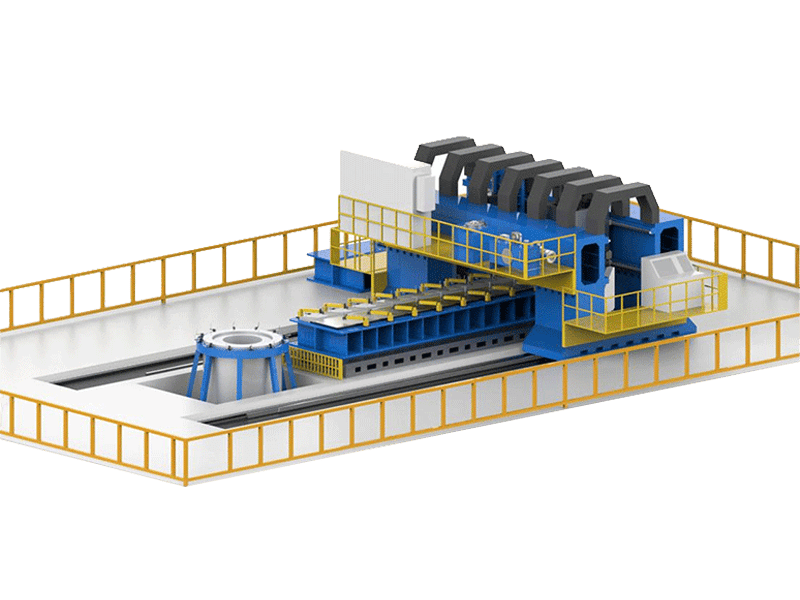
For high-volume bridge panel production, a fully automatic double-head production line can weld long straight aluminum profiles with automatic tracking, clamping, and discharge. Supplied capability includes weld thickness from 1.2 mm to 16 mm, a maximum weld length of 18.5 m, and a maximum panel width of 3.5 m. Automation becomes valuable when the same profile family repeats across a bridge project because the process database and clamping cycle can be reused.
Backing, Clamping, and Thermal Management
Backing is not an accessory in FSW; it is part of the joint support system. The rotating tool applies a large downward force and a traverse force, so the panel must be held against a rigid backing bar or anvil close to the weld line. The backing also removes heat from the back side and helps prevent the softened material from being extruded into a gap or forming an incomplete root. Backing material, contact pressure, and any groove or no-groove detail must be defined for the actual profile.
Clamping must be specified as carefully as the weld parameters. A long deck extrusion can rise or buckle locally if the clamps are too widely spaced. The clamping plan should keep the joint closed along the full weld length, allow enough clearance for the tool and shoulder, and account for thermal expansion during welding. Run-on and run-off tabs are commonly used so the start and end transients fall outside the finished component.
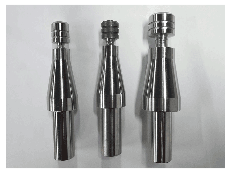
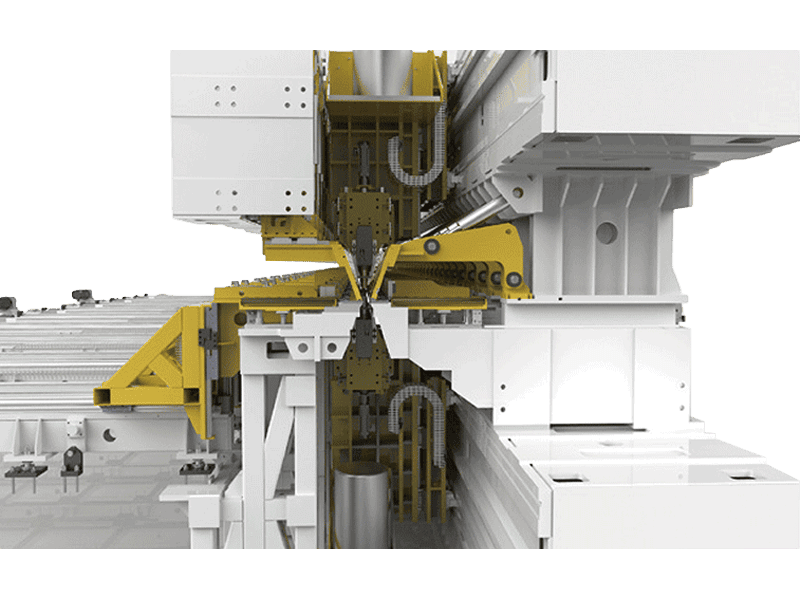
When the back side cannot be supported with a conventional backing bar, a bobbin tool uses two shoulders on opposite sides of the workpiece and can weld hollow sections or long closed profiles without a separate back support. The welding thickness range is narrower than a heavy single-shoulder setup, so the design team should compare the flexibility benefit against the thickness limit before locking the profile geometry.
Thermal management also affects flatness. Because FSW heats only a narrow band, wide panels still need sequenced welding and periodic dimensional checks. A panel that is welded on one side only may pull out of plane after clamp release. The weld sequence and any post-weld straightening or machining allowance should be written into the fabrication plan.
Qualification and Inspection for Civil Projects
A structural FSW procedure is not the same as a demonstration weld. The fabricator must qualify the procedure on the same alloy, temper, thickness, joint type, tool, machine class, and backing concept intended for production. The starting point is the governing aluminum welding code or client specification. That document drives the required test types, the number of coupons, and the acceptance limits for discontinuities.
The inspection plan should be written for FSW rather than copied from a fusion-welding porosity table. FSW discontinuities include incomplete penetration, wormhole or tunnel defects along the weld path, root flaws, surface flash, and embedded tool fragments. Visual inspection can find surface flash, cracking, and gross underfill, but volumetric checks are needed for internal tunnel and root conditions. Phased-array ultrasonic testing can be used to interrogate the joint from the accessible face, while radiography and destructive sectioning support process development and production audits. The final NDT method must match the joint geometry and the flaw orientation the client needs to detect.
Before production begins, the supplier should produce a first-article panel with instrumented logs of spindle speed, travel speed, axial force, and tool number. That panel goes through destructive and non-destructive testing, and the accepted parameters are locked into the production procedure. Periodically repeating a reduced destructive test program gives the owner evidence that the process has not drifted as tool, backing, or fixture wear changes the weld condition.
When FSW Is Not the Right Choice for a Bridge Project
FSW has clear limits in bridge and civil work. The most important is site access. FSW requires a rigid machine, high axial force, and controlled travel, so it belongs in a fabrication hall rather than as an on-site joining method for a final field splice. Site connections are normally bolted or use another accepted process after the FSW-welded panels are transported.
FSW also becomes difficult when the joint is highly curved in three dimensions, when the weld line passes over a deep internal void without a designed backing path, or when the fit-up is so variable that the gap cannot be closed consistently. A fatigued repair on a thin, previously welded structure may also be a poor candidate because the repair needs clean, supported parent metal and a new qualification.
Cost is a practical constraint. A dedicated FSW machine is a capital investment, and its value depends on repeat panel production. For a one-off repair or a small quantity of irregular members, the qualification and tooling cost can exceed the benefit. The decision should be made on total project cost, including fixturing, sample welding, NDT, and requalification, not on weld cost per meter alone.
Feasibility and Supplier Selection Before Buying
The most useful feasibility study starts with the actual extrusion drawing. Send the profile cross-section, alloy and temper, weld length, thickness, joint type, required code, and inspection class to the machine supplier before asking for a price. A reliable supplier can then confirm whether a standard long-seam or gantry machine fits the part, or whether the profile needs a redesigned backing path or a different tool concept.
Ask for a sample weld on a production-intended machine, not a small laboratory unit with different stiffness. The sample should be sectioned and tested, and the machine should log the parameters from the run. Compare the logged axial force and spindle torque against the machine’s rated capacity with a reasonable margin. Confirm that the clamping, backing, tool change, and operator training are included in the proposal rather than treated as separate unknowns.
Finally, verify the after-sales plan. Long bridge programs depend on spare tools, spindle support, remote diagnostics, and a documented service response. A supplier that can provide a complete machine and process package reduces the risk of qualifying a weld that cannot be repeated when the project moves from prototype to production.
Plan Your First Bridge Panel Feasibility Study
The next step is to send the real project inputs: profile drawing, alloy and temper, weld length, maximum thickness, joint type, governing code or client inspection class, and annual volume. Those inputs let a supplier confirm the right machine class, propose a backing and tool concept, and scope a sample-welding program. Contact Aerospace Engineering Equipment (Suzhou) Co., Ltd. at [email protected] or +86 18325808715 with the profile data and the intended production target.
FAQ
Can FSW be performed on-site for bridge structures?
Not for the primary structural seams. FSW needs a rigid machine bed, high axial force, and controlled travel, so it is a shop fabrication process. Bridge components are welded in a factory as panels or profiles, then transported and connected on site with bolted splices or another accepted site joining method.
What aluminum alloys are best for bridge and civil FSW?
5xxx plate and 6xxx extrusions are the most common practical choices. 5xxx alloys provide corrosion resistance but require design to the as-welded strength after cold-work loss. 6xxx extrusion alloys combine good formability with reliable FSW, but the process zone softens from the original temper. 7xxx alloys can be used when the project justifies the narrower process window and additional qualification.
How thick can FSW weld an aluminum bridge structure?
It depends on the machine and joint design. Supplied long-profile capability in this article is 8 mm for an extra-length seam, while wide panel gantry capability reaches 25 mm, and a heavy-load supplied machine can weld 100 mm aluminum from one side or 190 mm from both sides. The real limit is set by machine force, spindle torque, backing, and the profile cross-section, not by the aluminum thickness alone.
Does FSW meet structural welding codes?
Yes, when it is qualified correctly. FSW is a solid-state process, so the procedure specification, test coupons, and acceptance criteria must follow a code or client specification written for FSW or approved as a special process. A fusion-welding WPS should not be reused as proof of FSW capability.
Why choose FSW over MIG or TIG for bridge deck panels?
FSW generally produces lower distortion, avoids filler-metal chemistry and porosity concerns, and gives repeatable long seams because the machine controls travel speed, spindle speed, and axial force. The tradeoff is that the panel must fit tightly, must be clamped and backed for high force, and must be welded on a suitable rigid machine rather than in the field.
If you’re interested, check out these related articles:
AEE attend 13th International Symposium on FSW in Kyoto, Japan on 21 – 23 May 2024
AEE provides customer with optional features FSW tool
Refill Friction Stir Spot Welding (RFSSW)