
Friction Stir Welding Copper: Parameters and Tool Materials
Table of Contents
- Copper FSW Is Not Aluminum FSW
- Copper Welding Parameters Follow a Narrow Window
- What rotation speed should copper FSW start from?
- Why does forge force matter more than travel speed?
- Tool Material Choice Determines Copper FSW Cost and Life
- Copper FSW Requires Force, Torque, and Thermal Control
- Copper FSW Feasibility Testing Should Come Before Equipment Investment
- Copper FSW Buyers Ask These Questions Before Ordering
- Can FSW weld copper busbar without preheating?
- Does copper FSW produce acceptable electrical conductivity?
- What copper thickness is realistic for FSW?
- How do we qualify a copper FSW process for production?
Friction stir welding copper is production feasible, but it does not behave like aluminum. The two most common reasons a copper FSW program stalls are spindle torque limits and tool wear, not the base material itself. Copper carries heat away from the weld zone far faster than aluminum, which changes the practical parameter window and places a hard load on the tool shoulder and pin. I have reviewed copper FSW trials where a workable process emerged only after lowering travel speed, raising forge force, and switching to a tool material that survived the thermal cycle. This article defines the operating window, machine requirements, and tooling decisions that determine whether copper FSW belongs in your process.
Copper FSW Is Not Aluminum FSW
Copper fails most aluminum FSW recipes because the thermal balance is different. Aluminum holds heat near the tool shoulder long enough to plasticize a wide zone. Copper moves heat into the surrounding part, so the plasticized region stays narrow and the tool must generate more local heat without overheating the shoulder. That difference raises spindle torque, shortens tool life, and makes the weld more sensitive to travel speed variation. It also changes the joint quality conversation. A copper FSW weld can show a fine recrystallized nugget and good electrical continuity, but only if the process avoids the flash, void, and lack of fill defects that appear when the tool outruns the material flow.
Copper Welding Parameters Follow a Narrow Window
Copper FSW parameters do not transfer from 6xxx aluminum. The starting point for thin copper sheet sits between a low rotation speed that keeps the tool from overheating and a travel speed that keeps the shoulder engaged. In process development we have run 3 mm to 5 mm copper with rotation speeds around 600 to 900 rpm and travel speeds around 75 to 120 mm per minute. Forge force stays high relative to aluminum because the copper resists deformation at the shoulder face. The parameter set only becomes stable when forge force, spindle speed, and travel speed move together, not when one value is adjusted in isolation.
What rotation speed should copper FSW start from?
For pure copper, start near 600 to 900 rpm and keep the shoulder plunge depth constant. Higher speeds oxidize the shoulder and raise the risk of tool softening. If the weld surface shows rough flash, reduce rotation speed before increasing travel speed. If the nugget shows lack of fill, raise forge force before changing the rpm.
Why does forge force matter more than travel speed?
Forge force sets the contact pressure between the shoulder and the workpiece. Copper has high hot strength, so the tool needs more axial load to keep the plasticized material contained. Too little force creates lack of fill and root voids. Once force is adequate, travel speed becomes the main lever for heat input. Adjust force first, then travel speed.
Tool Material Choice Determines Copper FSW Cost and Life
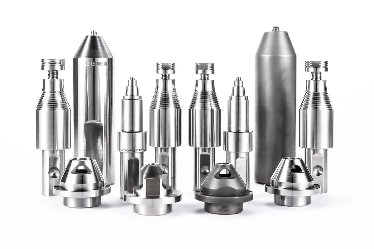
Copper FSW tooling is a consumable decision, not a one-time selection. The tool shoulder runs hot because the material pulls heat away from the pin. A tool steel shoulder that works in aluminum can soften early in copper service. The economic choice is not always the hardest material. It is the material that reaches an acceptable number of weld meters before the tool geometry changes enough to affect joint quality.
| Tool material | Behavior in copper FSW | Practical use | Main failure mode |
|---|---|---|---|
| H13 tool steel | Loses hardness at elevated shoulder temperature | Short trials, thin copper sheet | Pin deformation, shoulder wear |
| Tungsten-based alloy | Keeps strength in hot copper, resists wear | Production busbars, thick sections | High material cost, limited toughness |
| Tungsten carbide | Very high hardness, low adhesion | Thin and medium copper sections | Chipping under high forge force |
| PCBN | Low reactivity, stable at high temperature | Long production runs, abrasive alloys | High initial cost, brittle |
Tool geometry matters as much as material. Copper wants a shoulder that contains the plasticized volume without dragging too much surface oxide into the joint. A slightly concave shoulder can improve material capture, but the same geometry can trap flash if the plunge depth drifts. We have seen copper FSW tools fail more often from shoulder capture problems than from pin wear. For closed welds, a retractable pin removes the exit hole. For thin sections, a stationary shoulder narrows the heat input band.
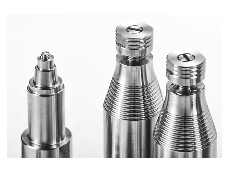
Copper FSW tooling often starts with a standard tool and then modifies shoulder features for a narrower heat input band. <AEE provides customer with optional features FSW tool> covers how optional pin and shoulder configurations are matched to a part before production.
If your copper joint is thicker than 6 mm or runs longer than 2 meters, confirm the spindle torque and tool cooling strategy before freezing a machine specification. We can check those values against your part geometry at [email protected].
Copper FSW Requires Force, Torque, and Thermal Control
Copper FSW makes a larger demand on the machine than most aluminum programs. The spindle must keep torque at the tool instead of stalling, and the Z-axis must hold a consistent forge force while the thermal field shifts. A light or medium FSW machine may be able to run a short copper sample, but it will not hold the process stable across a production-length weld if the force or spindle temperature drifts.
For thicker sections, the machine envelope has to cover the entire weld. The AEE heavy-load FSW machine carries a 105 kW spindle with 872 Nm torque and a 200 kN maximum Z-axis force. That envelope covers single-side copper welds up to 35 mm, far beyond what general-purpose aluminum welding cells can maintain. The same machine uses force control and position control with integrated data acquisition, so the copper process does not depend on the operator holding a setting by eye.
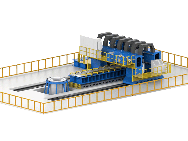
Thermal management is just as important as spindle power. Copper FSW tooling needs controlled cooling at the tool holder or spindle interface, and the fixture must not pull so much heat from the weld that the root fails to close. Backing bars with lower conductivity can retain enough heat at the root without starving the nugget, but the bar material has to be changed when the copper thickness changes.
Copper FSW Feasibility Testing Should Come Before Equipment Investment
Copper is not the place to buy a machine on a data sheet. A short feasibility weld exposes the real capacity gap: how much torque the spindle draws at the target plunge depth, how fast the tool loses geometry, and whether the fixture holds the copper part without thermal distortion. It also produces a sample that can be sectioned, conductivity-tested, and leak-tested or bend-tested before a production line is budgeted.
Start with the part geometry and the most difficult weld position. If a program has a long straight copper busbar, test the full cross-section at the longest continuous weld length the production line will see. If the part has a closed loop, use a retractable-pin tool and measure the exit-hole fill. If the copper is joined to aluminum, add a dissimilar-material coupon to the same trial because the interface behaves differently from either base material.
Copper FSW is not only a single-material process. Busbar and battery tab programs often mix aluminum and copper in one assembly. <Customized Dissimilar Material Welding Manufacturers in China> covers how a welding supplier manages joint design and tooling when two thermally different materials share a weld interface.
Copper FSW programs stall most often at the feasibility stage because teams bring aluminum FSW data and try to extend it to copper. The parameter window is narrower, the thermal load on the tool is higher, and the spindle force requirement can exceed what a general-purpose machine delivers. AEE runs copper FSW feasibility trials on heavy-load equipment with force and temperature monitoring, so the decision to buy or outsource is based on measured joint results rather than extrapolation.
If you have a copper part drawing and a target weld length, share the material grade, thickness, and required joint configuration with [email protected] or call +86 18325808715. We will confirm the tooling strategy and whether your weld envelope fits a standard machine or a customized copper FSW cell.
Copper FSW Buyers Ask These Questions Before Ordering
Can FSW weld copper busbar without preheating?
Yes. FSW does not require preheating because the shoulder generates the heat directly in the material. The constraint is spindle torque, not preheat. For thick busbar sections the machine must hold enough forge force to keep the root closed while the shoulder travels. If the torque reserve is too low, the process will stall even though the part is at room temperature.
Does copper FSW produce acceptable electrical conductivity?
A common concern is that FSW leaves high-resistance oxides in the joint. In a sound weld the rotating shoulder breaks and redistributes the surface oxide rather than trapping it as a continuous film. The recrystallized nugget can show slightly higher resistivity than annealed base metal, but the difference is usually small enough for busbar and connector service. For critical electrical parts, conductivity testing belongs in the feasibility plan.
What copper thickness is realistic for FSW?
It depends on the copper alloy and the available spindle torque. Pure copper conducts heat quickly, so thick sections need a high-torque spindle and a stiff fixture. Dispersion-strengthened copper can behave differently because it retains more hot strength. The practical upper range is not set by the process alone. It is set by whether the machine can deliver enough force and torque without degrading the tool.
How do we qualify a copper FSW process for production?
In copper projects I have reviewed, qualification starts with a frozen tool design, followed by a short weld matrix that varies rotation speed, travel speed, and forge force within the target envelope. The accepted settings are sectioned and tested before any fixture is finalized. Share your copper grade, part thickness, and joint configuration with [email protected] and we will confirm which qualification tests match your application and whether leak testing or conductivity testing should be added.
If you’re interested, check out these related articles:
AEE attend 13th International Symposium on FSW in Kyoto, Japan on 21 – 23 May 2024
AEE provides customer with optional features FSW tool
Refill Friction Stir Spot Welding (RFSSW)