
Friction Stir Welding 7075 Aluminum: Avoiding Hot Cracks
Table of Contents
- Why Does 7075 Aluminum Crack More Than 6061 in Fusion Welding?
- How Does Parameter Control Prevent Hot Cracking in 7075 Aluminum FSW?
- Why do rotation speed and travel speed have to move together?
- What axial force and tilt angle keep the tool engaged?
- What Tool Design Works for 7075 Aluminum Friction Stir Welding?
- How Much Heat Input Can 7075 Aluminum Accept Before Properties Drop?
- Does forced cooling change the outcome?
- Should you re-heat-treat after welding?
- How Do You Lock a Repeatable 7075 FSW Parameter Window?
- What Questions Do Manufacturers Ask About Welding 7075 with FSW?
- Can FSW weld 7075-T6 without losing strength?
- What is the biggest mistake buyers make when specifying 7075 FSW?
- Does the exit hole matter for 7075 structures?
- How do we qualify the process before committing to production equipment?
Friction stir welding 7075 aluminum changes the cracking conversation completely. Unlike fusion processes, FSW never melts the base material, so the solidification cracking that makes 7075 difficult with MIG or TIG largely disappears. The remaining risks shift to heat input, tool selection, and post-weld property loss, especially in T6 temper. A repeatable 7075 FSW process depends less on one universal speed and more on holding the material inside a narrow thermal window while matching the pin profile to the thickness. This article covers that window from the equipment and process side.
Why Does 7075 Aluminum Crack More Than 6061 in Fusion Welding?
The short answer is chemistry and solidification range. 7075 is an Al-Zn-Mg-Cu alloy with a wider freezing range and a higher tendency for interdendritic liquid films than 6061. When a fusion arc melts the joint, copper and zinc segregate at grain boundaries, and the last liquid to solidify cannot accommodate shrinkage. The result is hot cracking, often through the weld centerline, and sometimes microfissures near the fusion line. FSW avoids that failure path because the process never creates a liquid pool. However, that does not make 7075 forgiving. The same alloy is precipitation hardened, so any thermal cycle hot enough to close the joint can soften the heat-affected zone and reduce strength from T6 levels. Engineers who treat 7075 like 6061 usually meet one of two problems: a good-looking weld with poor tensile performance, or a process that starts well and drifts out of control as the tool wears.
How Does Parameter Control Prevent Hot Cracking in 7075 Aluminum FSW?
With no solidification cracking, parameter control focuses on two things: keeping the material plasticized enough to flow without overheating, and keeping the tool engaged so the weld root is complete. In our development work, 6 to 12 mm 7075-T6 usually responds well to rotation speeds from about 300 to 600 rpm and travel speeds from 50 to 200 mm per minute, depending on shoulder diameter and pin geometry. The exact window changes with thickness, backing plate material, and whether the plate is in T6 or an overaged condition.
Why do rotation speed and travel speed have to move together?
A low rotation speed with a high travel speed can leave an unwetted root or tunnel defect because the material does not plasticize deeply enough. A high rotation speed with a low travel speed pushes heat input up, widens the softened zone, and can produce excessive flash while lowering joint strength. The practical control is not to chase maximum speed from the start. It is to hold the ratio between rotation and travel constant while monitoring spindle torque and Z-axis force. A stable torque trace usually matters more than a high travel speed number.
What axial force and tilt angle keep the tool engaged?
For 7075, I prefer to keep axial force on the higher side of the machine capability at first, typically in the range the spindle and fixture can hold without part lift. A one to three degree tilt angle puts more forging pressure at the trailing edge of the shoulder. The exact tilt depends on shoulder concavity and pin length. If the part is thin, reduce tilt before reducing force. A small change in one parameter changes the temperature field enough to move the weld out of tolerance, so qualified settings should be recorded as a set, not as individual values.
What Tool Design Works for 7075 Aluminum Friction Stir Welding?
Tool selection for 7075 is a compromise between wear resistance, heat generation, and surface finish. The pin must survive the high zinc and copper content of the alloy while maintaining enough material flow to fill the weld root. A threaded, tapered pin with a concave shoulder works well for butt joints in the 4 to 12 mm range. Threads drive material downward and close the root, while the concave shoulder contains the plasticized surface and reduces flash.
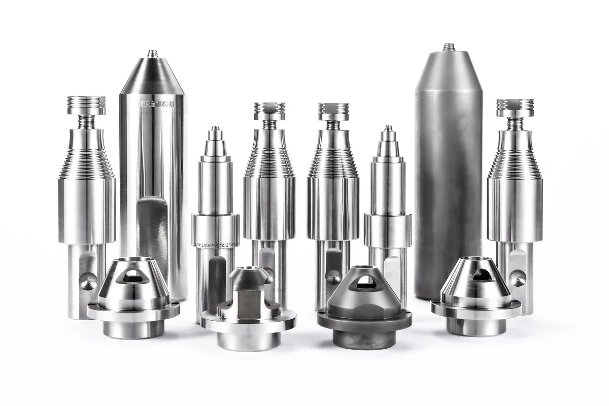
Tool holder geometry also influences how much bending moment reaches the pin. <AEE provides customer with optional features FSW tool> covers why optional tool features are evaluated against a specific alloy and thickness range before quoting, not after the first weld trial.
For 7075, tool steel may work for short trials, but production runs often move to a more wear-resistant pin material because the alloy is abrasive and the process temperature is high. The shoulder should be selected to keep the surface heat input from becoming excessive. A larger shoulder generates more frictional heat, which is useful for thick sections but harmful for thin sheet.
If your program involves 7075 plates thicker than 10 mm, confirm the tool holder interface and spindle torque capacity before you freeze the fixture plan. Send your part number and thickness to [email protected] and we can check which pin and holder combination fits the machine you are specifying.
How Much Heat Input Can 7075 Aluminum Accept Before Properties Drop?
The practical limit for 7075-T6 is not the melting temperature; it is the overaging temperature. T6 strength depends on fine precipitates. When the weld cycle holds the heat-affected zone above roughly 150 to 180 degrees Celsius, precipitates coarsen and tensile properties fall. That is why a slower travel speed can produce a metallurgically sound weld that still fails below base metal strength in the heat-affected zone. The best FSW results for 7075 usually show failure in the nugget or the TMAZ boundary, not excessive HAZ softening.
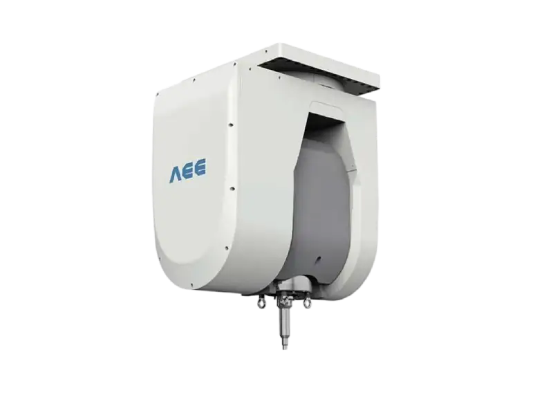
Spindle selection matters here because the machine must hold torque and speed stable while the process runs inside that window. A spindle that cannot maintain speed under load produces a wandering thermal profile.
| Spindle model | Welding thickness | Max speed | Torque | Max Z-axis force |
|---|---|---|---|---|
| AEE-S125 | 1 to 8 mm | 4000 rpm | 112 Nm | 30 kN |
| AEE-S119 | 2 to 12 mm | 4000 rpm | 208 Nm | 40 kN |
| AEE-S112 | 2 to 16 mm | 2500 rpm | 208 Nm | 50 kN |
| AEE-S065 | 2 to 25 mm | 2000 rpm | 257 Nm | 60 kN |
| AEE-S076 | 2 to 40 mm | 1500 rpm | 482 Nm | 80 kN |
Does forced cooling change the outcome?
For 7075, forced cooling can be useful in thick sections. A water-cooled backing plate or forced air on the weld surface pulls heat out faster and can narrow the softened zone. It also adds complexity to the fixture and can create distortion if only one side is cooled. I treat cooling as a stabilization method after the parameter window is already close, not as a fix for a bad parameter set.
Some 7075 assemblies mix alloys at stiffening members or closeout welds. <Customized Dissimilar Material Welding Manufacturers in China> covers why tool geometry and parameter validation change when a weld line crosses from one aluminum grade to another.
Should you re-heat-treat after welding?
Re-solutionizing and re-aging can restore much of the T6 strength, but it also changes dimensions and adds cost. For many structural applications, the better route is to accept a lower post-weld strength and design the joint with enough margin. The decision should be made before the first weld, not after the tensile test surprises someone.
How Do You Lock a Repeatable 7075 FSW Parameter Window?
A repeatable production process needs more than a successful lab coupon. It needs recorded parameters, a defined tool change interval, and an inspection method that can catch the defects 7075 tends to produce when the tool starts to wear. The first step is to weld enough coupons to establish the relationship between spindle torque, Z-axis force, and weld appearance. Record these traces for every coupon. When the torque signature changes by more than a few percent at the same speed and force target, stop and inspect the pin.
Use destructive tensile tests and macro sections early, and keep at least one reference coupon from each production run. For 7075, I also check the exit hole and the first 50 mm of the weld, because the start and end of the pass run cooler than the middle. A retractable pin tool avoids the keyhole and is worth considering for closed welds, but it adds tool complexity. If a fixed pin is used, start and stop tabs are cheap insurance.
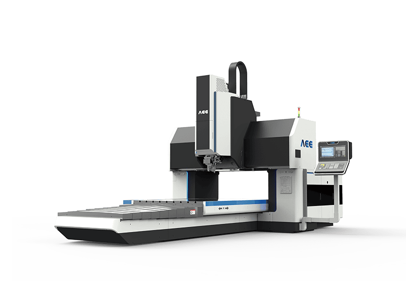
The difficulty with 7075 is not that FSW cannot weld it; it is that each parameter set, tool geometry, and spindle choice interacts in a way that is easy to underestimate. AEE has run development programs across C-type, gantry, and heavy-load FSW platforms, and we have the spindle torque and Z-axis force data to match a machine to your part rather than forcing your part onto a standard setting. Send your part print, target thickness, and production volume to [email protected] or call +86 18325808715, and we will confirm the parameter window and tool strategy for your first qualification batch.
What Questions Do Manufacturers Ask About Welding 7075 with FSW?
Can FSW weld 7075-T6 without losing strength?
Yes, but a friction stir weld in 7075-T6 seldom reaches full base metal strength unless the part is re-solutionized and re-aged after welding. In the as-welded condition, the heat-affected zone softens because the thermal cycle coarsens the strengthening precipitates. In development coupons we have tested, joint efficiency typically falls between roughly 70 and 85 percent of base metal tensile strength, with thicker plates usually at the lower end when heat builds up. Engineers should design around the post-weld temper condition, not the mill certificate value.
What is the biggest mistake buyers make when specifying 7075 FSW?
The biggest mistake is treating machine specification as the only variable that matters. Spindle torque and travel speed matter, but pin geometry, backing plate condition, and tool wear monitoring decide whether the process stays repeatable after the first few parts. Buyers sometimes lock a machine size before checking the tool interface and then discover the spindle cannot hold the required aluminum alloy process window under continuous load. Order the sequence the other way: define the weld, pick the tool, then size the machine.
Does the exit hole matter for 7075 structures?
It depends on whether the weld is linear or closed. For linear seams, start and stop tabs let the keyhole fall outside the finished part, so a conventional pin is usually sufficient. For circumferential or enclosure welds, the keyhole becomes a defect risk. A retractable pin tool withdraws the pin into the shoulder as the pass ends and fills the exit, leaving a sealed joint without a through-hole. The retractable design costs more and needs a machine with the right control axis, but it eliminates a secondary plug or repair operation.
How do we qualify the process before committing to production equipment?
In our qualification programs, the sequence moves from sample welding, to coupon testing, to a small pre-production run. First we weld enough coupons to lock rotation speed, travel speed, and Z-axis force. Then we cut macro sections and run tensile tests to confirm the nugget, TMAZ, and HAZ behavior. Only after that data looks stable do we move to a short production run with the same tooling and fixture. Share your part print and target thickness with AEE at [email protected], and we will confirm which spindle and pin geometry we have already qualified for that range.
If you’re interested, check out these related articles:
Refill Friction Stir Spot Welding (RFSSW)
AEE attend 13th International Symposium on FSW in Kyoto, Japan on 21 – 23 May 2024
Customized Dissimilar Material Welding Manufacturers in China
AEE provides customer with optional features FSW tool