
Friction Stir Welding 6061 Aluminum: Parameters and Strength
Table of Contents
- Why 6061-T6 Loses Strength in Conventional Welding
- FSW Parameters That Control 6061 Joint Strength
- Rotation Speed and Travel Speed in 6061
- Axial Force, Tilt, and Tool Plunge
- Defect Detection for 6061 Friction Stir Welds
- Matching 6061 FSW Parameters to Application Requirements
- Thin-Wall Water Cooling Plates and Battery Tray Covers
- Structural Profiles and Enclosures
- Equipment and Tooling Decisions That Protect 6061 Weld Quality
- Planning a 6061 FSW Qualification
- Common Questions About Friction Stir Welding 6061 Aluminum
- How strong is an FSW joint in 6061-T6 compared with fusion welding?
- Does 6061 aluminum require preheating before FSW?
- Which FSW machine size is appropriate for 6061 prototypes versus high volume?
- Where do most 6061 FSW qualification programs go wrong?
Friction stir welding 6061 aluminum produces joints with tensile strength around 70 to 80 percent of the T6 base metal, but only when heat input stays inside a narrow band. Engineers planning EV battery trays, water cooling plates, or structural profiles rarely get that result from a generic parameter table. A more useful question is which parameter combination prevents heat-affected zone softening without inviting tunnel defects. More than fifteen years of process development work in our Suzhou and Liyang plants points to controlled travel speed, sufficient Z-axis force, and tool geometry matched to the temper rather than the alloy alone.
Why 6061-T6 Loses Strength in Conventional Welding
6061 aluminum is a heat-treatable Al-Mg-Si alloy. In T6 temper, most of its strength comes from fine Mg2Si precipitates that form during artificial aging. Fusion processes such as MIG or TIG push the weld zone well above the 582°C solidus, and the heat-affected zone on both sides spends enough time above about 250°C to coarsen those precipitates. The result is a welded joint that often measures 50 to 65 percent of base metal tensile strength, plus porosity, hot cracking, and angular distortion. That loss is metallurgical, not a problem better filler wire can solve.
Friction stir welding does not melt the joint. The rotating tool plasticizes the metal, and peak temperatures in the nugget generally stay between 450°C and 520°C, below the solidus. This removes porosity and hot cracking from the process window. However, the thermomechanically affected zone and heat-affected zone still experience a thermal cycle. If rotation speed is too high or travel speed too low, the HAZ will overage anyway, pulling 6061-T6 back down toward the annealed condition. In our tensile testing, correctly parameterized FSW joints in 6061-T6 typically retain 70 to 80 percent of base metal strength, while the soft HAZ remains the fracture location. That is the main performance gap a parameter strategy has to manage.
FSW Parameters That Control 6061 Joint Strength
Because 6061-T6 is precipitation hardened, the winning parameter set is not the one that maximizes tensile strength in a single test coupon. It is the one that keeps nugget consolidation and HAZ cooling balanced across production tolerances. For a 6 mm 6061-T6 butt joint in a rigid fixture, the starting ranges below cover most of the parameter combinations we use before fixture and tool adjustments.
| Parameter | Practical starting range | Main effect on a 6061-T6 joint |
|---|---|---|
| Rotational speed | 800 to 1400 rpm | Controls heat generation; too high overages the HAZ, too low leaves wormhole defects |
| Travel speed | 150 to 400 mm/min | Higher speed shortens the thermal cycle but raises tool force and root-defect risk |
| Z-axis force | 12 to 24 kN | Inadequate force produces flash and incomplete consolidation; excessive force thins the joint |
| Tilt angle | 1 to 3 degrees | Maintains forging pressure at the tool rear; excess tilt thins the retreating side |
| Pin tool plunge depth | 0.1 to 0.3 mm below shoulder contact | Controls surface flash and nugget fill; too deep increases underfill on the exit side |
Rotation Speed and Travel Speed in 6061
On 6 mm 6061-T6 battery tray extrusions, travel speed has produced a larger strength change in our trials than a 10 percent shift in rotation speed. Moving from 250 to 350 mm/min while holding rotation near 1200 rpm shortened HAZ residence time enough to lift tensile results by 8 to 12 percent in some tests. The tradeoff is force. Faster travel demands more axial force and a stiffer fixture. If the machine cannot hold the set force, the tool rides up and produces a shallow root face. We therefore set travel speed based on the machine force ceiling first, then tune rotation speed to surface finish and crown quality.
Axial Force, Tilt, and Tool Plunge
Force control matters more than a fixed plunge depth in 6061. The material softens quickly once the tool shoulder engages, so a machine running position control alone can lose forging pressure as the plate heats. We use Z-axis force as the primary control and let plunge depth float inside a narrow tolerance. That approach keeps the shoulder in contact with plasticized material without overplunging the advancing side. Tilt angle between 1 and 3 degrees is enough to move the shoulder pressure toward the rear of the tool. Beyond 3 degrees the root face on the retreating side usually thins.
Defect Detection for 6061 Friction Stir Welds
6061 is more forgiving than 2xxx or 7xxx alloys, but the same three production defects still appear: tunnel or wormhole voids on the advancing side, root lack of penetration from a short pin or low force, and surface flash from overplunging. We classify them separately because the corrective action is different.
Tunnel defects appear on the advancing side when the tool moves too fast for the available heat and forging force. In cross-section they look like a small cavity just below the weld crown. They seldom heal after the tool passes. Root flaws are different: a shallow pin or a machine force that drops below command leaves an unconsolidated line at the joint bottom. Tunnel defects require either slower travel or higher rotation. Root defects require pin length and force correction. Mixing them up is the most common qualification error we see from teams new to FSW.
For 6061 structural parts, we combine visual inspection for flash and crown symmetry with phased array ultrasonic testing for tunnel and root flaws. X-ray works on thinner sections but becomes less useful above 8 mm because density changes are small. Mechanical testing confirms tensile and bend performance on first-article parts. A single bend or macro etch can reveal incomplete penetration, but it will not catch intermittent tunnel defects across a full production run.
Matching 6061 FSW Parameters to Application Requirements
A single parameter window does not fit every 6061 aluminum product. Thin-wall cooling plates tolerate low force and high travel speed. Structural profiles and battery enclosures need longer pin length and more heat input. The application drives tool design before machine settings.
Thin-Wall Water Cooling Plates and Battery Tray Covers
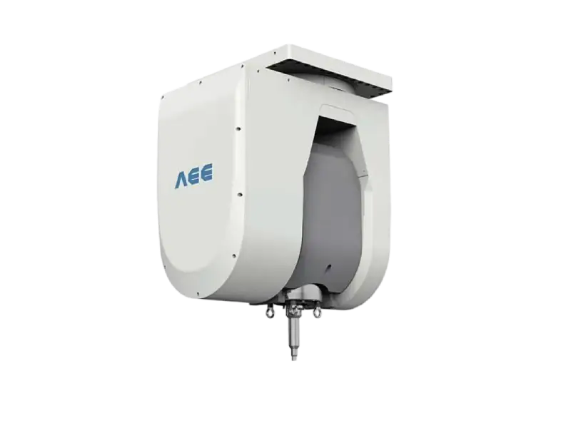
For 1.5 to 3 mm 6061-O or T6 sheet used in cooling plates, heat input must stay low enough to avoid burn-through and surface deformation. We reduce shoulder diameter, move to a stationary shoulder or small conventional shoulder, and keep travel speed above 300 mm/min. On the AEE C-type platform, process development for 6 mm 6061 water cooling plates runs up to 3500 mm/min in welding speed when the fixture and thermal backing are correct. The strength target in these parts is usually leak tightness and flatness, so start and exit strategies matter more than maximum tensile strength.
Structural Profiles and Enclosures
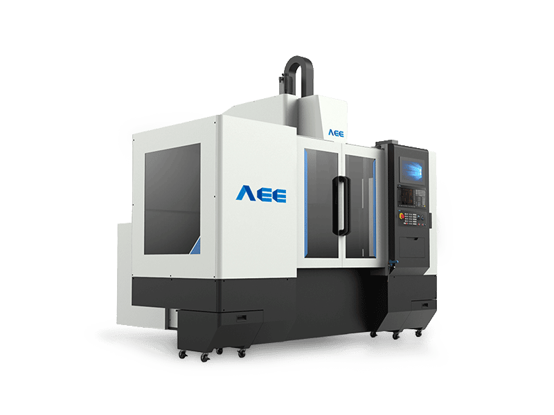
Battery trays and enclosure frames made from 6 to 12 mm 6061-T6 extrusions need a different parameter profile. Pin length and shoulder diameter both increase, and axial force moves into the upper end of the machine capability. Gantry machines with 30 kN to 60 kN Z-axis capacity handle this class well because force control remains stable over 2 to 4 meter weld lengths. For long extrusions, a small tilt error or fixture drift creates a 0.5 mm root shift by the end of the weld. We use laser seam tracking and constant force control rather than relying on taut plate alignment.
Most battery tray programs start with 6061 extrusions but later add copper busbar or dissimilar material joints. <Customized Dissimilar Material Welding Manufacturers in China> explains why dissimilar joints need a different tool wear and intermetallic control strategy before they are added to a production line.
Equipment and Tooling Decisions That Protect 6061 Weld Quality
6061 aluminum welds best on a machine that holds force tightly and does not flex under tool pressure. The spindle bearings and C-axis take a steady bending load, so a rigid frame is more important than maximum spindle speed. Spindle torque in the 100 to 250 Nm range covers most 6061 applications from 3 to 16 mm. Welding speed and force requirements define the upper boundary.
Tool type is the second decision. Conventional tapered threaded pin tools cover most 6061 butt and lap joints. Retractable tools eliminate the exit hole for closed-loop battery tray covers and water-cooled enclosures, while stationary shoulder tools reduce heat input and flash on thin-wall parts. We treat these as process options, not premium upgrades, because the choice changes the parameter window and the qualification test plan.
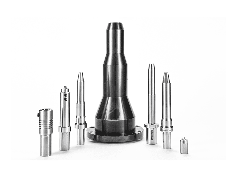
The same machine can move between conventional and optional tool forms if the spindle interface is specified from the beginning. <AEE provides customer with optional features FSW tool> covers how optional tool features such as retractable pins and stationary shoulders affect what can be qualified on a single spindle.
Planning a 6061 FSW Qualification
Most 6061 FSW programs do not fail because the process is unproven. They fail because the first part is ordered with the wrong force range, the fixture is designed for a different thickness, or the acceptance criteria for HAZ softening were never agreed. Fixing a parameter window before the machine ships saves weeks.
Send your part drawing, temper, weld length, and required monthly throughput to [email protected]. We will return a practical parameter window, a machine and tooling recommendation, and a qualification test plan you can compare against your own fixture costs. For production timeline and after-sales questions, call +86 18325808715. If the application includes leak-tight enclosures or closed contours, include the required leak rate and the exit-hole condition. That detail determines whether the process needs a retractable tool from the start.
Common Questions About Friction Stir Welding 6061 Aluminum
How strong is an FSW joint in 6061-T6 compared with fusion welding?
A properly made FSW joint in 6061-T6 typically reaches 70 to 80 percent of base metal tensile strength, while a MIG or TIG joint often lands between 50 and 65 percent. The difference comes from reduced porosity, no solidification cracking, and less severe HAZ overaging. In bend testing, FSW also retains more ductility because the weld nugget has a fine recrystallized grain structure rather than a cast dendritic structure. The actual number depends on tool geometry and the parameter window, not on the process label alone.
Does 6061 aluminum require preheating before FSW?
No. Preheating usually works against the FSW process. The tool already generates the required heat through friction and plastic deformation, and external preheat widens the HAZ and accelerates precipitate coarsening. The only case where we consider preheating is for very thick sections or long travel distances where the machine cannot generate enough heat, but even then we prefer adjusting rotation speed or changing the shoulder design first.
Which FSW machine size is appropriate for 6061 prototypes versus high volume?
It depends on weld length and throughput. A compact C-type machine with 30 kN Z-axis force handles 6 mm 6061 prototype coupons and small water cooling plates. Gantry machines make more sense for battery trays or profiles longer than 2 meters because they keep force stable across the weld. For consistently high throughput, dual-worktable or automated production line configurations cut load and unload time, but the parameter window must be locked before adding that automation.
Where do most 6061 FSW qualification programs go wrong?
In qualification programs we have managed, the most common failure is not selecting the wrong weld parameters. It is qualifying on rigid short coupons and then running the same settings on a long flexible component with different clamping. The tool then plunges deeper, force changes, and a root flaw appears in production that the coupon test missed. We recommend running the first article on a fixture that represents production clamping, not a vise. If your first article inspection shows inconsistent root profiles, send us your parameter log and cross-section images. We can identify whether the issue is tool geometry or clamping before you run more trials.
If you’re interested, check out these related articles:
Refill Friction Stir Spot Welding (RFSSW)
Customized Dissimilar Material Welding Manufacturers in China
AEE attend 13th International Symposium on FSW in Kyoto, Japan on 21 – 23 May 2024