
European EV Supplier FSW Production Line: AEE Case Study
Table of Contents
- What Did the European EV Supplier Need from the FSW Production Line?
- Why Did the Buyer Choose a Turnkey Line Instead of a Standalone Machine?
- How Do Machines, Tooling, and Automation Fit Together in an FSW Production Line?
- Why Does Tooling Change More Than the Welding Head?
- What Functions Are Automated on the Line?
- What Process Control Keeps an FSW Production Line Stable?
- What Do Welding Pressure and Laser Tracking Catch?
- How Should a Buyer Start Scoping a Similar FSW Production Line?
- What Do Buyers Want to Know Before Finalizing an FSW Production Line?
- How Fast Does the Wheel Line Run?
- Does the Line Need a Different FSW Tool for Each Part Family?
- How Is No-Keyhole Welding Handled on a Cylindrical Part?
- What Should I Send to Get a Feasibility Answer?
Most friction stir welding equipment decisions fail long before installation, on the gap between machine capability and production line integration. A European EV supplier moving to in-house welding did not buy a standalone FSW machine; it scoped a complete FSW production line, including automatic loading, clamping, weld start positioning, friction stir welding, inline inspection, and unloading. The differentiator was not a higher spindle rating. It was how the line held process conditions constant across shift changes and hundreds of identical parts. That is the lens this case study uses to break down what to specify, what to check, and where costs actually appear.
What Did the European EV Supplier Need from the FSW Production Line?
The production requirement was narrower than a general FSW capability statement and harder to execute. The line had to weld aluminum hub and cylinder components with material thickness from 1.2 mm to 10 mm and wheel diameters from 17 to 22 inches. Within that envelope, the process had to produce a stable circumferential weld at up to 2.5 m/min, with spindle rotation up to 6000 rpm, and hold a cycle rate of 45 joints per hour.
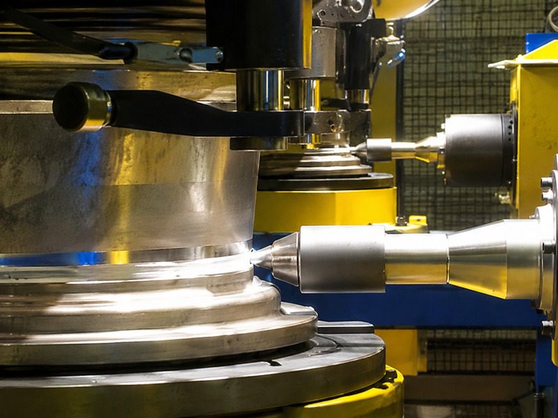
Those numbers matter because they set the automation requirement. A line can hit 45 joints per hour only if loading, clamping, weld start positioning, welding, and unloading repeat without operator delay. The European customer therefore scoped the line for unmanned operation: robot loading and unloading, QR code scanning for part traceability, automatic identification and positioning, and separation of finished and reject parts without manual sorting.
The buyer also needed the line to store weld recipes instead of requiring a process engineer to re-enter parameters for every wheel family. The specialized HMI and process database on the line let operators select a part program, after which feeding, clamping, welding, and outfeed run from the stored recipe.
Why Did the Buyer Choose a Turnkey Line Instead of a Standalone Machine?
A standalone FSW machine removes the welding bottleneck but leaves three other bottlenecks in place. The operator still has to present the part, hold the joint in position, and decide whether the finished part is acceptable. For a European EV supplier running production shifts, those manual steps control the real cycle time and the real scrap rate.
By moving to an automated FSW production line, the buyer shifted the constraint from operator speed to machine and fixture repeatability. The line runs the same loading and clamping sequence on every cycle, which reduces variation in joint fit-up before the tool enters the weld. That fit-up consistency matters more than spindle speed because a small shift in clamping changes frictional contact, plunge depth, and flash formation.
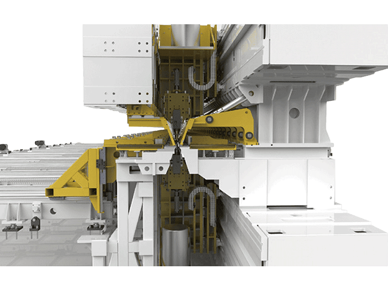
Cycle time was also a decision trigger. At 45 joints per hour, there is no time for an operator to inspect, mark, and sort each wheel. The line needed automatic weld quality judging and outfeed. Without that function, labor cost would rise and throughput would fall even if the welding spindle were faster.
How Do Machines, Tooling, and Automation Fit Together in an FSW Production Line?
The machine frame gives the line its stiffness and stroke. The tooling gives it weldability across the part range. The automation gives it repeatability. Buyers who fixate on spindle power usually miss the interaction among the three.
On this line, the welding envelope is 1.2 mm to 10 mm in material thickness, with wheels from 17 to 22 inches. The machine uses constant pressure welding and laser tracking to hold the tool on the joint even when the circumferential path shifts slightly. The line also uses retractable FSW tooling, so the exit hole disappears as the pin withdraws into the shoulder at the end of the weld. That removes a post-weld drilling or repair step on a cylindrical wheel.
| Line function | What it controls |
|---|---|
| Robot loading and unloading | Part flow without manual handling |
| Wheel disc and rim clamping | Joint fit-up and runout before welding |
| Laser tracking with weld start positioning | Tool location on the circumferential path |
| Welding quality judging | Separation of finished and reject parts |
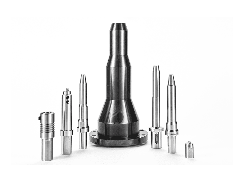
On a production line, tool choice changes cycle time, weld start behavior, and keyhole management as much as the machine frame does. <AEE provides customer with optional features FSW tool> covers the practical options to specify before freezing a line layout, including no-keyhole retraction features.
The line is delivered with CE safety and ISO9001 quality documentation, which matters when the buyer’s audit team reviews the installation before SOP approval.
Why Does Tooling Change More Than the Welding Head?
The pin and shoulder determine material flow, surface finish, and tool life. A retractable pin solves the exit-hole problem on a closed circumferential weld. If the buyer had used a fixed-pin tool, every wheel would need a runout tab or a secondary repair. The retractable tool turns a circumferential weld into a sealed joint without a keyhole.
What Functions Are Automated on the Line?
QR code scanning records which wheel family is entering the line. The system then selects the weld recipe from the process database, positions the start point, applies constant pressure, and judges quality after welding. Finished and reject parts separate automatically, so the shift report is based on recorded results rather than operator judgment.
What Process Control Keeps an FSW Production Line Stable?
A production line is stable when the welding pressure, joint position, and quality judgment stay consistent on every cycle. The line runs constant pressure welding, displays welding pressure, and uses laser tracking to hold the tool on the joint. It also stores weld recipes and quality results in the process database, so each wheel carries a traceable record. In lines I have scoped, the most useful early warning has been torque drift at constant traverse speed. It shows up before surface flash and gives the team time to check tool wear before parts become scrap.
Laser tracking and welding pressure display give the operator a direct check on joint tracking and upset force. The line keeps weld start point positioning under machine control, so the seam begins at the same location on every wheel. That is more difficult than it sounds on a round part, because a small rotation error moves the start point by the full error multiplied by the radius.
Constant pressure welding compensates for small variation in clamping and part height. Position control alone cannot do that, because circumferential welding on a thin web or rim moves slightly under thermal expansion. The line therefore combines pressure control with laser tracking and tool retraction to keep the weld continuous and keyhole free.
If your program stretches across multiple wheel diameters, mixed weld depths, or a new joint design, it is worth confirming the clamping strategy and tool retraction sequence before the BOM is frozen. Send the part cross-section and target throughput to [email protected], and the engineering team can check which functions are required and which are optional.
What Do Welding Pressure and Laser Tracking Catch?
Welding pressure logs catch clamping drift and plunge depth changes. Laser tracking catches lateral movement of the joint path. A rising pressure trace at fixed plunge usually indicates a fit-up change, while a wandering laser signal often points to part runout. Together they turn a visual weld defect into an early process excursion that can be corrected before a full shift of scrap is produced.
How Should a Buyer Start Scoping a Similar FSW Production Line?
The most expensive scope mistakes happen before a single drawing is sent. A buyer lists material and weld depth, then discovers during factory acceptance that clamping pressure, part runout, or cycle time does not fit the line. That late change is far more expensive than a feasibility check on the front side.
Start with four inputs: the part drawing, the joint configuration, the annual volume, and the target cycle rate. Each of those changes a different part of the line. Part drawing changes tooling and fixture clearances. Joint configuration changes retractable versus fixed pin, and shoulder geometry. Annual volume changes the level of automation and whether dual workstations or a full line is justified. Target cycle rate determines loading, clamping, and inspection functions.
Send those four inputs with your part cross-section and production target to [email protected] or +86 18325808715. AEE will confirm which line configuration, tooling, and inspection functions fit the scope before you commit to a machine layout.
What Do Buyers Want to Know Before Finalizing an FSW Production Line?
How Fast Does the Wheel Line Run?
The line reaches 45 joints per hour on aluminum wheel and cylinder components, with welding speed up to 2.5 m/min and spindle rotation up to 6000 rpm. Those are production numbers, not laboratory numbers. Actual throughput still depends on part diameter, wall thickness, and how quickly the fixture settles after loading. The line is designed for unmanned operation, so the rated rate assumes automatic loading, clamping, welding, and outfeed rather than manual part handling.
Does the Line Need a Different FSW Tool for Each Part Family?
Not necessarily. A common assumption is that every part number requires a dedicated tool, but the more useful question is whether the tool must change for different thicknesses and joint types. Conventional, retractable, bobbin, and stationary shoulder tools cover different ranges, so a wheel line often runs one primary tool geometry with adjustments to pin length and shoulder diameter. The process database stores each recipe, and tool change occurs only when geometry changes enough to affect material flow.
How Is No-Keyhole Welding Handled on a Cylindrical Part?
It depends on the joint path. For a full circumferential weld, the retractable FSW tool is the standard choice because the pin withdraws into the shoulder at the end of the weld and leaves a filled surface. The line uses that approach to avoid an exit hole on wheels, so no runout tab or post-weld drilling is needed. For linear seams or open profiles, a fixed-pin tool may be acceptable because the exit hole can be placed outside the part or trimmed.
What Should I Send to Get a Feasibility Answer?
The feasibility check is only as good as the information you send. Instead of a general machine quote, send the part drawing, joint configuration, annual volume, and target cycle rate. Add the material grade and the rejection criteria you use for weld surface, strength, and leak rate. With those inputs, AEE can confirm which machine frame, tool, clamping method, and inspection functions fit the line. Send those inputs to [email protected], and the team will confirm whether a line matches your scope.
If you’re interested, check out these related articles:
Refill Friction Stir Spot Welding (RFSSW)
Customized Dissimilar Material Welding Manufacturers in China
AEE provides customer with optional features FSW tool
AEE attend 13th International Symposium on FSW in Kyoto, Japan on 21 – 23 May 2024