
Custom FSW Solutions: Early Supplier Input Reduces Risk
Table of Contents
- Custom FSW Solutions Begin With a Defined Production Requirement
- Collaborative FSW Projects Expose Risks Before the Machine Order Is Placed
- Material and Joint Decisions Need Process Windows Confirmed by the Supplier
- Custom Machine Specifications Require Validation on Actual Part Geometry
- Documented Acceptance Criteria Remove Ambiguity From Final Buyoff
- Procurement Teams Ask These Questions Before Signing a Custom FSW Order
- How early should the FSW supplier be involved in a custom project?
- Does a standard machine work for custom FSW applications?
- What should we submit with the first RFQ to get a useful quotation?
- What if our part design changes after the machine order?
- What proof should we ask for before final acceptance?
A custom FSW machine that misses one process boundary can turn a six month procurement into a year of rework. Custom FSW solutions reduce that risk when the supplier is brought into feasibility work before the equipment specification is frozen. In fifteen years of friction stir welding equipment development, the largest schedule and cost overruns I have seen came from decisions that were locked before anyone confirmed the weld could be produced. This article does not treat custom FSW as a catalog option. It explains how early supplier input shortens the path from part drawing to production through requirement definition, feasibility testing, process window confirmation, machine validation, and documented acceptance.
Custom FSW Solutions Begin With a Defined Production Requirement
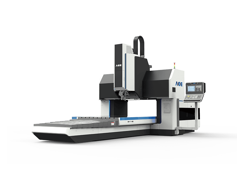
Most custom FSW inquiries start with a machine type request: a buyer asks for a gantry machine, a C-type machine, or a robotic system before the weld requirement is defined. That sequence creates risk because the machine architecture should follow the part geometry, material stack-up, annual volume, and joint condition. A 10 meter rail profile and an EV battery tray are both aluminum, but they generate very different machine structures.
| Requirement category | What to specify before quoting | Why it changes the machine |
|---|---|---|
| Part geometry and weld path | Envelope dimensions, weld length, 2D or 3D curvature | Selects C-type, gantry, extra length, or 3D architecture |
| Material stack-up | Alloy series, thickness, dissimilar combinations | Sets spindle torque, power, and tool material |
| Joint type and access | Butt, lap, T-joint, closed contour, single or double side | Changes clamping, backing, and tool selection |
| Production volume and cycle time | Parts per day, required JPH, loading method | Drives dual worktable, double head, or automatic line |
| Quality and data requirement | NDT method, leak test, process traceability | Adds force and torque logging and inspection integration |
A 55,000 square meter production footprint does not remove the need for a clear requirement. We separate fixed constraints, such as maximum weld thickness and part length, from preferences, such as a specific controller brand. When both are treated as equal, the machine builder designs around assumptions instead of measured requirements. That is where custom FSW projects begin to drift.
Collaborative FSW Projects Expose Risks Before the Machine Order Is Placed
The point of early supplier work is not extra documentation. It is to fail early on low cost trial sections instead of failing late on a commissioned machine. We test weld coupons and representative part sections before finalizing axis strokes, clamping force, and tool geometry. A 7075 aluminum weld can show a clean top surface and still contain an internal tunnel defect when axial force is too low. A 6xxx battery tray can pass a first article and then produce flash at production speed. Both failures are cheaper to find on a trial fixture than during final acceptance.
In our feasibility work, we have rejected more parts for clamping deflection than for spindle power. That observation changes the conversation. A buyer who focuses only on motor size may miss the fixture and backing design that actually controls weld quality at the intended travel speed. Early supplier input turns those hidden conditions into measured requirements.
Material and Joint Decisions Need Process Windows Confirmed by the Supplier
Material selection is not a machine detail. It defines the process window. 5xxx and 6xxx aluminum are forgiving in friction stir welding, but 2xxx and 7xxx aerospace alloys demand tighter heat input control, and copper requires a different torque band than aluminum of the same thickness. A machine sized for 6xxx battery tray welding may be marginal for 25 mm copper busbar work. Dissimilar joints, especially aluminum to copper or aluminum to steel, add intermetallic growth as a time-temperature constraint. A supplier who confirms these boundaries before quoting can tell you whether a stationary shoulder design, reduced rotation speed, or higher axial force is required.
When aluminum is joined to copper or another dissimilar metal, the process window cannot be copied from a single-material weld. <Customized Dissimilar Material Welding Manufacturers in China> covers how intermetallic control changes tool geometry and parameter selection, which is often the hidden risk in battery busbar and cooling plate projects.
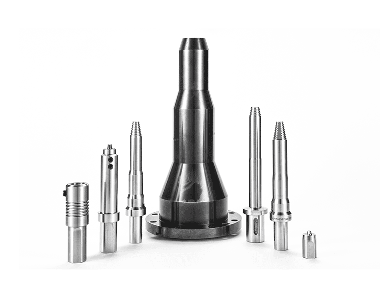
Tool selection follows the same logic. Retractable tools close keyholes in closed contours. Bobbin tools weld hollow profiles without a backing anvil. Stationary shoulder designs reduce surface flash and heat input. Each choice changes cycle time, tool life, and machine force requirements.
If your custom FSW project involves 7xxx aluminum, a dissimilar material joint, or a leak tight battery enclosure, it is worth confirming the process window before finalizing the machine specification. Send the part material, thickness, and weld path to [email protected] or call +86 18325808715, and request a feasibility position before the RFQ is locked.
Custom Machine Specifications Require Validation on Actual Part Geometry
A machine can meet every catalog specification and still be wrong for the part. The part is clamped first. The tool must reach every weld line without collision. The force path must stay rigid at the travel speed the part requires. For a 6xxx aluminum plate at 8 mm, a 12 kW spindle with 112 Nm torque and 30 kN Z-axis force may be enough. For a 100 mm single side aluminum weld, the spindle moves to about 105 kW and 200 kN maximum force. That is not an upgrade option. It is a different machine class.
| Spindle model | Welding thickness | Torque | Maximum force | Power |
|---|---|---|---|---|
| AEE-S125 | 1 to 8 mm | 112 Nm | 30 kN | 12 kW |
| AEE-S119 | 2 to 12 mm | 208 Nm | 40 kN | 25 kW |
| AEE-S112 | 2 to 16 mm | 208 Nm | 50 kN | 25 kW |
| AEE-S065 | 2 to 25 mm | 257 Nm | 60 kN | 31 kW |
| AEE-S076 | 2 to 40 mm | 482 Nm | 80 kN | 58 kW |
| AEE-S064 | 2 to 100 mm | 874 Nm | 200 kN | 105 kW |
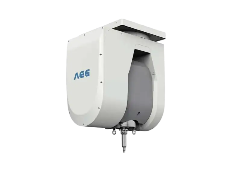
Tooling and spindle interface decisions are part of the same validation. A borderline part can sometimes be brought into a stable process window with a different tool geometry rather than a complete machine redesign.
When the weld requirement sits close to a machine’s upper force or speed boundary, small tooling choices matter more than the machine brochure. <AEE provides customer with optional features FSW tool> covers how a tool modification, rather than a complete machine redesign, can bring a borderline part inside a stable process window.
Documented Acceptance Criteria Remove Ambiguity From Final Buyoff
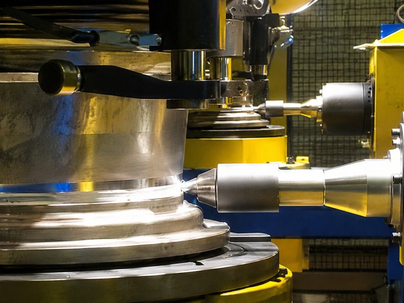
The final risk point is acceptance. A vague statement that the machine must weld with good quality transfers uncertainty from the supplier to the buyer. Instead, define acceptance around measurable outputs: weld penetration, tensile or shear performance, leak test results, cycle time at target parameters, and repeatability over a defined sample count. On a fully automatic wheel production line, acceptance can include cycle time at 45 JPH, retractable tool keyhole behavior, and weld traceability. On a battery tray line, the focus may be leak proofing, tool changes, and data logging continuity.
Procurement risk usually comes from awarding a contract before the machine has been matched to the part. The lower-risk path is to treat the first weld trials as the purchasing decision, not as a post-order activity. If you are evaluating custom FSW solutions, send your part drawing, required weld length, production rate, and quality target to [email protected] or call +86 18325808715. We will confirm feasibility and proposed acceptance criteria before you commit to a machine architecture.
Procurement Teams Ask These Questions Before Signing a Custom FSW Order
How early should the FSW supplier be involved in a custom project?
Bring the supplier in before the RFQ is issued. Early input from us usually starts with a review of the part drawing and weld requirements, not a quotation. If the supplier only sees a finished specification, it can confirm whether that specification is buildable but cannot identify cheaper or lower-risk alternatives. Early involvement creates room to adjust joint design, choose a suitable machine architecture, and avoid paying for travel strokes or spindle capacity the part does not need.
Does a standard machine work for custom FSW applications?
A common assumption is that a custom FSW part requires a fully bespoke machine. That is not true. Custom work can mean selecting a proven C-type or gantry platform and adding the right fixture, tooling, or data logging set. The problem appears when a standard frame is stretched past its useful force range to save budget. That choice reduces spindle rigidity and process stability, and the savings disappear in rejected parts and rework.
What should we submit with the first RFQ to get a useful quotation?
It depends on whether you are quoting the machine only or the machine plus process. At minimum, send the weld path drawing, material grade and thickness, required joint type, and annual volume. For machine plus process work, add the required cycle time, leak or NDT criteria, and a sample part if possible. With the part sample, we can produce a feasibility weld and return a quotation based on measured parameters rather than estimated values. Without the joint details, any quotation is a placeholder.
What if our part design changes after the machine order?
In programs we have supplied, a late part change is most expensive when the machine frame was sized to a single envelope. A change from a 1,200 mm weld length to a 1,600 mm weld length may exceed the original X-axis stroke and cannot be recovered with software or a new fixture. We ask customers to separate likely change from fixed change. For likely change, we leave a defined amount of travel or force margin. For fixed change, we document the condition so that the acceptance criteria stay clear.
What proof should we ask for before final acceptance?
Before final acceptance, the question to ask is not whether the machine runs, but whether it runs your part. We recommend a documented sample weld report before shipment and a repeatability run after installation. The report should include weld cross sections, tensile or leak results, recorded force and torque, cycle time, and any macro or NDT inspection agreed in the purchase specification. This evidence ties the machine to your part, not to a generic demonstration coupon. Share your required test plan at [email protected] or +86 18325808715, and we will confirm what can be demonstrated with your part before final acceptance.
If you’re interested, check out these related articles:
AEE provides customer with optional features FSW tool
AEE attend 13th International Symposium on FSW in Kyoto, Japan on 21 – 23 May 2024
Refill Friction Stir Spot Welding (RFSSW)