
Aluminum to Steel FSW: Controlling Intermetallic Formation
Table of Contents
- Why Aluminum-to-Steel FSW Fails Without Intermetallic Control
- Which Intermetallic Compounds Form and When Do They Become a Risk?
- Which Intermetallic Phase Causes the Most Problems?
- How Does the Intermetallic Layer Change Joint Failure Mode?
- How Should Tool Offset and Heat Input Be Controlled When Welding Aluminum to Steel?
- Why Is the Pin Usually Offset Toward the Aluminum Side?
- What Do You Need to Qualify Aluminum-to-Steel FSW for Production?
- How Do You Move From Coupon Trials to a Production-Ready Aluminum-to-Steel Process?
- What Do Engineers Ask Before Starting Aluminum-to-Steel FSW?
- Can aluminum-to-steel FSW replace all fusion welding or mechanical fastening in a joint?
- Does the steel side need to be preheated before welding?
- Which matters more, the aluminum grade or the steel grade?
- What is the fastest way to confirm whether a specific aluminum-to-steel stack-up will work?
Aluminum-to-steel FSW only becomes production-ready when the intermetallic layer is treated as a controlled process output rather than an unavoidable defect. Most failed qualification coupons come from trying to run aluminum-to-steel welds with aluminum-to-aluminum habits: the same rotation speed, the same tool offset, and the same assumption that a clean surface is enough. In dissimilar friction stir welding, some Fe-Al intermetallic phases will form at the interface. The engineering goal is to keep that layer thin, discontinuous, and mechanically stable. That requires a different tool path, a tighter thermal window, and a machine stiff enough to hold the pin where it belongs.
Why Aluminum-to-Steel FSW Fails Without Intermetallic Control
Aluminum-to-steel friction stir welding fails through a different mechanism than most aluminum-to-aluminum welds. The aluminum side plasticizes and flows under the shoulder, but the steel side remains below its own plastic deformation point. Bonding therefore relies on a combination of steel fragments mixed into the aluminum matrix and a diffusion layer at the interface. When the interface temperature is too high or the dwell time too long, that layer becomes a continuous brittle band. When it is too cold, the steel side never bonds enough and the joint behaves like an incomplete mechanical lock.
The practical problem is that ordinary FSW habits push the process toward the first failure mode. High shoulder engagement, slow travel speed, and a pin buried deep into the steel all raise the interface temperature. A welder developing the joint with aluminum-only logic will see a visually full weld and still get low bend performance because the crack starts at the interface rather than in the aluminum. This is why the first qualification rule is to stop treating aluminum-to-steel FSW as an aluminum welding process with a harder backing plate.
Which Intermetallic Compounds Form and When Do They Become a Risk?
At the aluminum-steel interface, the main intermetallic phases form when iron and aluminum diffuse into each other. The table below summarizes what matters for weld evaluation.
| Phase | Formation condition | Practical effect |
|---|---|---|
| FeAl3 | Aluminum-rich side of the interface, usually at lower diffusion temperature | Brittle layer that is most damaging when it forms as a continuous band |
| Fe2Al5 | Fast-growing phase when the interface becomes hot | Often the dominant brittle constituent; cracks easily under tensile or peel loading |
| FeAl | Higher-temperature or higher-shear zone with more steel mixing | Harder and less harmful when dispersed, but indicates a higher-energy process |
Which Intermetallic Phase Causes the Most Problems?
The phase that causes the most failures in our testing is not a single phase but a continuous Fe2Al5-rich band. Isolated intermetallic particles can sit inside the aluminum matrix without dominating fracture. The problem starts when particles link into a layer that gives the crack a continuous low-energy path. In a well-controlled weld, intermetallic formation is inevitable; the objective is to keep it discontinuous and thin rather than trying to make a completely phase-free interface.
How Does the Intermetallic Layer Change Joint Failure Mode?
A sound aluminum-to-steel weld fails with ductile tearing in the aluminum sheet. Once the intermetallic layer becomes continuous, failure changes to brittle interface separation with lower elongation and highly variable bend results. Tensile strength may still look acceptable in a small coupon because the aluminum section carries much of the load, but peel, fatigue, and thermal cycling expose the brittle layer quickly. That is why tension testing alone is not enough to qualify this joint type.
How Should Tool Offset and Heat Input Be Controlled When Welding Aluminum to Steel?
Tool offset is the first variable to fix because it controls how much steel the pin stirs and how much unoxidized iron becomes available for reaction. In many butt and lap configurations, the pin is positioned with most of its stirring action on the aluminum side while the pin tip or a small side edge grazes the steel. This keeps steel fragments small and prevents the interface from becoming an oversized reaction zone.
| Parameter | Typical direction for aluminum-to-steel FSW | Why it matters |
|---|---|---|
| Pin offset | Shallow into the steel side or directly at the interface | Limits steel mixing and keeps the intermetallic layer discontinuous |
| Rotation speed | Lower than aluminum-to-aluminum settings | Lowers the peak interface temperature |
| Travel speed | Higher while machine force and tracking remain stable | Shortens the time at reaction temperature |
| Shoulder engagement | Reduced | Lowers surface heat input on the aluminum side |
| Cooling | Workpiece or fixture cooling when the cycle allows | Cuts dwell time above the temperature where Fe2Al5 grows rapidly |
There is no universal offset value because sheet thickness, steel coating, and lap geometry change the thermal balance. In development work, I run a small offset matrix first rather than sweeping rotation and travel at random. That separates mixing effects from heating effects quickly and shows whether the joint is sensitive to pin position or mainly to thermal history.
Why Is the Pin Usually Offset Toward the Aluminum Side?
The pin is offset toward the aluminum side because the aluminum must supply most of the plasticized flow. If the pin sits equally in both materials, the steel side can generate excessive heat from friction and tool wear without developing the same degree of plastic flow. Shallow steel engagement gives enough iron for mechanical and chemical bonding while keeping the steel fragment size small.
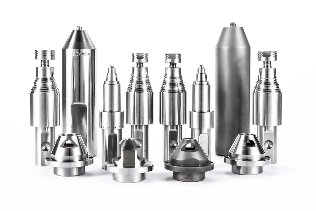
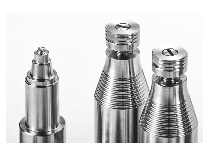
If the steel side is galvanized or coated, <AEE provides customer with optional features FSW tool> covers how optional pin and shoulder features are matched to specific joint configurations.
What Do You Need to Qualify Aluminum-to-Steel FSW for Production?
Qualification for aluminum-to-steel FSW should include more than a tensile test. A coupon can reach an acceptable ultimate tensile strength and still fail early in bend, fatigue, or corrosion because a thin intermetallic band is present. Cross-section metallography belongs in the development loop from the start, not after the first parts are welded. A micrograph shows whether steel fragments are dispersed or whether a continuous bright layer has formed along the interface.
Bend testing is usually more revealing than tensile testing for this joint because it applies controlled strain directly across the interface. A joint that carries tension through the aluminum sheet may still crack at a small bend angle when the interface layer is brittle. The exact test standard depends on the part requirement, but the sample configuration should force the crack path to cross the dissimilar interface rather than leaving it entirely in the aluminum.
If your program involves coated steel, changing sheet thickness, or a lap and fillet condition that alters heat extraction, it is worth confirming the tool offset and thermal management before finalizing the bill of materials. Send the stack-up drawing, material grades, and production rate to [email protected]; the resulting development plan will be more specific than a generic feasibility claim.
For programs where the joint stack-up is not a standard aluminum-to-steel butt or lap configuration, <Customized Dissimilar Material Welding Manufacturers in China> covers how co-engineering drives tool design and fixture choices before a machine platform is specified.
How Do You Move From Coupon Trials to a Production-Ready Aluminum-to-Steel Process?
Coupon trials show whether a material combination can be welded. They do not show whether a production cell can hold the required thermal and positional conditions for thousands of cycles. The common failure is a good coupon produced on a development machine that cannot be repeated on a production fixture with different clamping, heat sinking, and operator involvement. That is why aluminum-to-steel FSW programs need to define the full machine envelope early: axial force reserve, spindle torque at low speed, fixture stiffness, and control response as the pin crosses from aluminum into steel.
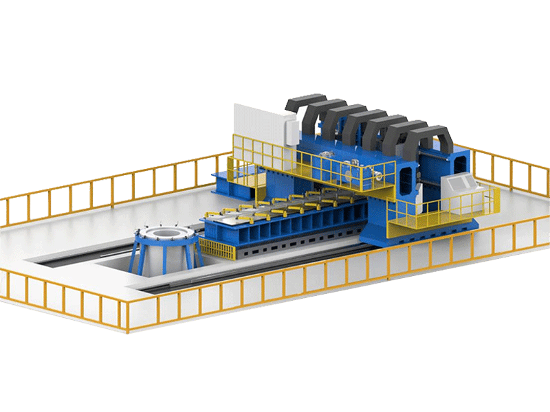
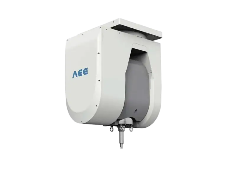
For high-force dissimilar work, a platform with 200 kN maximum Z-axis force and 872 Nm spindle torque gives more than enough force reserve for development; those are the values on our heavy-load gantry machine. For thin steel sheet, a stationary shoulder tool rated for steel from 1.0 to 10.0 mm changes the heat input profile enough to matter.
Before committing to a line, send the material grade, sheet thickness, joint configuration, and monthly volume to [email protected] or call +86 18325808715. The first step should be a small feasibility weld with pre-agreed acceptance criteria: tensile strength relative to the aluminum base metal, bend angle, and microstructural limits. That gives you a decision basis for machine selection, tooling, and fixture design instead of extrapolating from a general FSW equipment leaflet.
What Do Engineers Ask Before Starting Aluminum-to-Steel FSW?
Can aluminum-to-steel FSW replace all fusion welding or mechanical fastening in a joint?
No, aluminum-to-steel FSW is not a universal replacement for fusion welding, rivets, or structural adhesive. It fits applications where the joint is accessible from one side, the steel thickness is within the tool and machine capability, and the part can tolerate the clamping forces. It is strongest when the aluminum side carries most of the load and the steel side is used as a stiff or high-strength member. For open sections with limited backing support, a fusion weld or mechanical fastening may remain the better choice.
Does the steel side need to be preheated before welding?
Some teams assume preheating the steel will improve mixing. In most thin-sheet aluminum-to-steel FSW work, preheating the steel moves the process in the wrong direction because it adds energy to the interface before the pin arrives. That extra energy can thicken the intermetallic layer and increase tool wear. Heating is more useful later in the process when it is applied selectively through shoulder design, rotational energy, or tool offset, and not through a general preheat cycle.
Which matters more, the aluminum grade or the steel grade?
It changes with the joint stack-up. For lap joints, the aluminum temper often matters more because it controls how the sheet flows and how strongly it resists the tool. A soft aluminum may extrude too much at the joint edges, while a high-strength temper may demand more downforce. For butt or fillet configurations, the steel surface condition and coating have a larger effect because they change heat generation and reaction behavior at the interface.
What is the fastest way to confirm whether a specific aluminum-to-steel stack-up will work?
The more useful question is what acceptance limits define “work” for your part. A material combination can produce a full-length weld that still fails your bend or fatigue requirement. The fastest path is a small feasibility weld with a fixed offset matrix and microstructural inspection, not a single best-effort sample. Share the joint drawing, material grades, and monthly volume with [email protected] or +86 18325808715, and we can confirm whether a feasibility weld is worth running and what to measure before machine selection.
If you’re interested, check out these related articles:
Refill Friction Stir Spot Welding (RFSSW)
Customized Dissimilar Material Welding Manufacturers in China
AEE provides customer with optional features FSW tool